
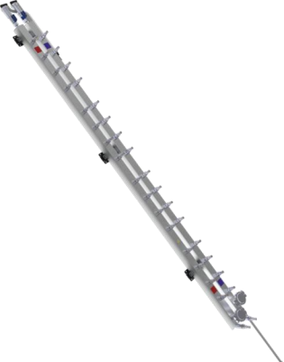
MF-DS · MF-BS
Manifold
The manifold is a water distribution and collection header for server liquid cooling, connecting the CDU to the cold plates of rack-mounted servers. It is available in quick-disconnect and blind-mate versions. It can be integrated into or externally connected to the cabinet frame, with branch flow selected according to server heat dissipation requirements.
Discuss this productFeatures & technical specifications2 specification tables
Product features
- 304 stainless-steel main body, air vent and related components; EPDM hoses for corrosion resistance.
- Pipeline design targets branch-flow non-uniformity below 10%.
- Customized for server layout and multiple cabinet mounting methods.
- In-cabinet installation operable by one person.
- Server branch connectors use drip-free quick connections for installation and maintenance.
- Deionized-water rinsing, high-temperature gas drying and transport under 1.5 bar gas pressure for cleanliness.
| Model family | Square-section specification (source notation) | Branch configuration | Material | Connection | Applicable fluid |
|---|---|---|---|---|---|
| MF-DS* | 30 × 30 | Customizable; standard 16 inlet + 16 outlet | SUS304 / SUS316L | Quick-disconnect | Ethylene glycol solution, propylene glycol solution, deionized water |
| MF-DS* | 40 × 40 | Customizable; standard 16 inlet + 16 outlet | SUS304 / SUS316L | Quick-disconnect | Ethylene glycol solution, propylene glycol solution, deionized water |
| MF-DS* | 50 × 50 | Customizable; standard 16 inlet + 16 outlet | SUS304 / SUS316L | Quick-disconnect | Ethylene glycol solution, propylene glycol solution, deionized water |
| MF-BS* | 30 × 30 | Customizable; standard 16 inlet + 16 outlet | SUS304 / SUS316L | Blind-mate | Ethylene glycol solution, propylene glycol solution, deionized water |
| MF-BS* | 40 × 40 | Customizable; standard 16 inlet + 16 outlet | SUS304 / SUS316L | Blind-mate | Ethylene glycol solution, propylene glycol solution, deionized water |
| MF-BS* | 50 × 50 | Customizable; standard 16 inlet + 16 outlet | SUS304 / SUS316L | Blind-mate | Ethylene glycol solution, propylene glycol solution, deionized water |
| Parameter | Typical source guidance |
|---|---|
| Server types | Rack-mounted liquid-cooled servers and blade liquid-cooled servers |
| Internal pipework | Stainless steel; sanitary clamp connections |
| Installation | Integrated into or externally connected to the cabinet frame |
| Branch flow | 1–4 L/min, based on server heat-dissipation requirements |
| Branch port diameter | Typically 3–6 mm, with matched quick connectors |
| Quick connector material | Typically stainless steel or aluminum |
| Example connector brands | Staubli, Parker, CPC |
| Air removal / drainage | Automatic air vent and drain |
| Branch regulation | No branch flow or temperature control |
| Typical fabrication | Constant-diameter stainless-steel square tubing |
| Typical branch count | 20 branches, supporting 20 servers per cabinet |
| Distribution arrangement | Typically one unit per cabinet; single server inlet and outlet |
| Branch connections | External threads; end caps applied at factory; G1/8 common according to server interface |
| Mounting | Generally at cabinet rear door, separate from PDU |
| Typical outer dimension | Approximately 33 × 33 mm |
Reference conditions & selection notes
- Slide 7 places branch configuration under the printed Material column and material under Number of Branches; the table above uses labels matching the actual cell content. Its printed Working Pressure column contains fluid names; no numeric working pressure is supplied.
- The slide 7 model series has standard 16-inlet/16-outlet configuration; slides 29–30 give separate typical engineering guidance of 20 branches. The typical guidance is not a rating for every MF model.
- The 30 × 30 / 40 × 40 / 50 × 50 source table does not print a dimension unit. The 33 × 33 mm example comes from slide 30.
Liquid Cooling Manual, pp. 6–7 and 29–30