Skip to content

Data center
cooling systems.

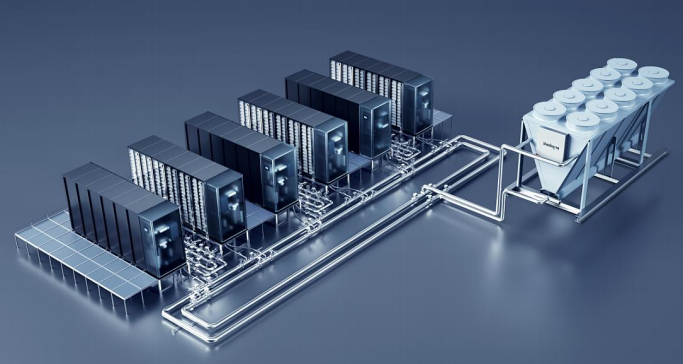
Complete liquid cooling architecture with rack equipment, distribution piping and outdoor heat rejection

01 / Precision air conditioning

Temperature and airflow.
Matched to the room.

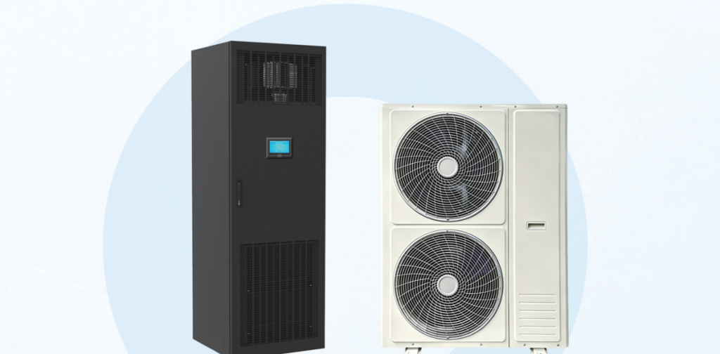
DC inverter compressors, EC fans and electronic expansion valves provide variable cooling output. Choose small-room, medium and large-room or in-row equipment, with the outdoor unit matched to site conditions.

6 equipment families / FSA, FMA, FRA, FCV, CAVR and FCM

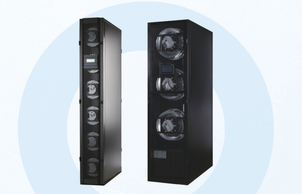
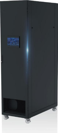
Small-room Precision Air Conditioner

FSA1008F/D · FSA1013F/D · FSA1020F/D

Small-room Precision Air Conditioner

The product uses a full DC inverter compressor, indoor EC speed-regulating fan, electronic expansion valve and condenser fan speed regulation to provide stepless cooling-capacity adjustment and 30% energy saving.

Discuss this product
Features & technical specifications4 specification tables

Product features

  • DC inverter compressor, indoor EC variable-speed fan, electronic expansion valve and variable-speed condenser fan provide stepless cooling capacity control and 30% energy savings.
  • Intelligent controls adjust fan speed to cooling demand, substantially reducing fan energy consumption.
  • Cooling/heating and constant-temperature-and-humidity configurations meet different application requirements.
  • Front top discharge, ducted top discharge and underfloor discharge support different airflow arrangements.
  • Components from established brands provide high reliability, a design life exceeding ten years and low maintenance costs.
  • A 4.3-inch touchscreen and multiple temperature and pressure sensors display unit operating status for operation and maintenance.
  • High airflow and a small enthalpy difference meet equipment-room requirements for a high sensible heat ratio.
  • Uses R410A refrigerant.
  • Automatically restarts after power restoration and resumes the operating state used before the outage.
  • Standard RS485 communication interface; a communication protocol can be supplied.
  • Extensive self-diagnostics, alarms and protection functions support safe, reliable operation.
Indoor unit specifications
ParameterFSA1008F/D (220V)FSA1008F/D (380V)FSA1013F/DFSA1020F/D
Cooling capacity (kW)7.87.813.220.8
Sensible cooling capacity (kW)7.57.512.620
Airflow (m³/h)2800280032007050
CompressorDC inverterDC inverterDC inverterDC inverter
Expansion deviceElectronic expansion valveElectronic expansion valveElectronic expansion valveElectronic expansion valve
Evaporator tubingInternally grooved copper tubeInternally grooved copper tubeInternally grooved copper tubeInternally grooved copper tube
Fan quantity1111
External static pressure (Pa)0~150Pa0~150Pa0~150Pa0~150Pa
Fan typeEC fanEC fanEC fanEC fan
Optional PTC electric heating capacity (kW)3333
Optional wet-film humidification capacity (kg/h)3333
Main power supply220V~/50Hz/1N380V~/50Hz/3N380V~/50Hz/3N380V~/50Hz/3N
Maximum distribution current (A)30121623
Recommended circuit breakerD32D16D25D32
Main power input cable3×65×45×65×6
RefrigerantR410AR410AR410AR410A
Indoor/outdoor connecting pipes and cables
ParameterFSA1008F/D (220V)FSA1008F/D (380V)FSA1013F/DFSA1020F/D
Liquid pipe diameter (mm)φ9.52φ9.52φ9.52φ12.7
Gas pipe diameter (mm)φ12.7φ12.7φ12.7φ16
Humidifier water inlet connection (mm)G1/2"G1/2"G1/2"G1/2"
Condensate drain pipe diameter (mm)25252525
Indoor/outdoor connecting cable3×1.53×1.53×1.54×1.5
Indoor/outdoor dimensions and gross weight
ParameterFSA1008F/D (220V)FSA1008F/D (380V)FSA1013F/DFSA1020F/D
Indoor dimensions, W × D × H (mm)660×555×1740660×555×1740660×555×1740750×730×1900
Outdoor dimensions, W × D × H (mm)960×390×810960×390×810960×390×12601070×990×1220
Indoor gross weight (kg)123123125190
Outdoor gross weight (kg)38385875
Outdoor unit specifications
ParameterFSA1008F/D (220V)FSA1008F/D (380V)FSA1013F/DFSA1020F/D
Outdoor unit quantity1111
Outdoor fan typeAxial fanAxial fanAxial fanAxial fan
Condenser tubingInternally grooved copper tubeInternally grooved copper tubeInternally grooved copper tubeInternally grooved copper tube

Applications

Small data centers · Telecommunications base stations · Small and medium computer rooms · Enterprise IT rooms · Rail transit · Equipment rooms · Substations · Laboratories

Precision Air Conditioning Manual, pp. 3–4
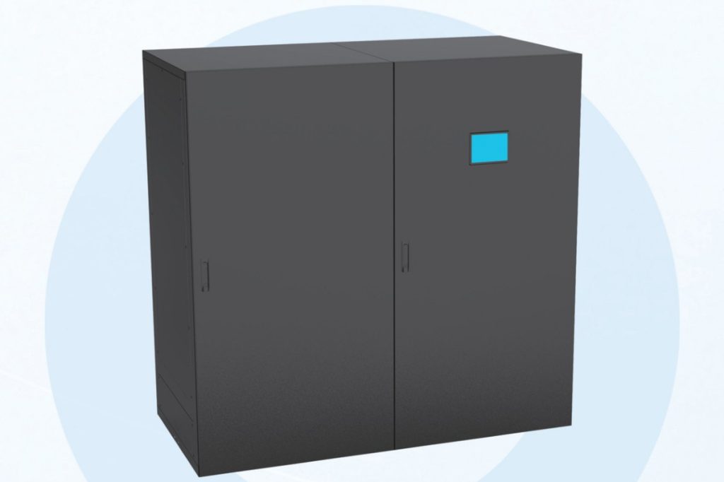
Medium and Large-room Precision Air Conditioner

FMAXXXXU/D Series

Medium and Large-room Precision Air Conditioner

This series uses a full DC inverter compressor, indoor EC speed-regulating fan, electronic expansion valve and condenser fan speed regulation. It has a modular structure with 100% front maintenance and can be installed side-by-side or against a wall.

Discuss this product
Features & technical specifications16 specification tables

Product features

  • DC inverter compressor, indoor EC variable-speed fan, electronic expansion valve and variable-speed condenser fan provide stepless cooling capacity control and 30% energy savings.
  • Modular construction permits 100% front access for maintenance and easy replacement, with no side service clearance; units can be installed side by side against a wall.
  • Intelligent controls adjust fan speed to cooling demand, substantially reducing fan energy consumption.
  • Cooling/heating and constant-temperature-and-humidity configurations meet different application requirements.
  • Front top discharge, ducted top discharge and underfloor discharge support different airflow arrangements.
  • Components from established brands provide high reliability, a design life exceeding ten years and low maintenance costs.
  • A 7-inch touchscreen and multiple temperature and pressure sensors display unit operating status for operation and maintenance.
  • High airflow and a small enthalpy difference meet equipment-room requirements for a high sensible heat ratio.
  • Uses R410A refrigerant.
  • Automatically restarts after power restoration and resumes the operating state used before the outage.
  • Standard RS485 communication interface; a communication protocol can be supplied.
  • Extensive self-diagnostics, alarms and protection functions support safe, reliable operation.
Single-circuit — general specifications
ParameterFMA1025U/DFMA1030U/DFMA1035U/DFMA1040U/DFMA1045U/DFMA1050U/DFMA1060U/D
Unit typeSingle-circuitSingle-circuitSingle-circuitSingle-circuitSingle-circuitSingle-circuitSingle-circuit
Main power supply380V 3PH-50Hz380V 3PH-50Hz380V 3PH-50Hz380V 3PH-50Hz380V 3PH-50Hz380V 3PH-50Hz380V 3PH-50Hz
Single-circuit — cooling performance
ParameterFMA1025U/DFMA1030U/DFMA1035U/DFMA1040U/DFMA1045U/DFMA1050U/DFMA1060U/D
Cooling capacity at 24°C / 50%RH (kW)25.530.036.040.045.550.061.0
Sensible cooling capacity at 24°C / 50%RH (kW)23.527.532.536.542.046.556.5
Cooling capacity at 35°C / 27%RH (kW)31.237.045.548.455.060.574.0
Sensible cooling capacity at 35°C / 27%RH (kW)31.237.045.548.455.060.574.0
Maximum operating current, FLA (A)38.340.844.352.055.257.866.7
Compressor quantity1111111
Single-circuit — indoor fan performance
ParameterFMA1025U/DFMA1030U/DFMA1035U/DFMA1040U/DFMA1045U/DFMA1050U/DFMA1060U/D
Circulation airflow (m³/h)800090001000011000120001350016000
Fan quantity1111111
Single-circuit — electric heating
ParameterFMA1025U/DFMA1030U/DFMA1035U/DFMA1040U/DFMA1045U/DFMA1050U/DFMA1060U/D
Heating capacity (kW)6669999
Single-circuit — humidifier performance
ParameterFMA1025U/DFMA1030U/DFMA1035U/DFMA1040U/DFMA1045U/DFMA1050U/DFMA1060U/D
Humidification capacity (kg/h)5555588
Single-circuit — indoor pipe connections
ParameterFMA1025U/DFMA1030U/DFMA1035U/DFMA1040U/DFMA1045U/DFMA1050U/DFMA1060U/D
Liquid pipe connection (mm)16161619191919
Gas pipe connection (mm)19191922222222
Condensate connection (mm)19191919191919
Humidifier water inlet (female connection)G1/2G1/2G1/2G1/2G1/2G1/2G1/2
Single-circuit — indoor dimensions and weight
ParameterFMA1025U/DFMA1030U/DFMA1035U/DFMA1040U/DFMA1045U/DFMA1050U/DFMA1060U/D
Length (mm)7008009001000100010001125
Depth (mm)1000100010001000100010001000
Height (mm)2000200020002000200020002000
Weight (kg)260305325350360380410
Single-circuit — recommended circuit breakers and cables
ParameterFMA1025U/DFMA1030U/DFMA1035U/DFMA1040U/DFMA1045U/DFMA1050U/DFMA1060U/D
Indoor circuit breaker (A)4P-40A4P-50A4P-50A4P-63A4P-63A4P-63A4P-80A
Indoor cable specification (mm²)3*6+2*43*10+2*63*10+2*63*16+2*103*16+2*103*16+2*103*16+2*10
Dual-circuit — general specifications
ParameterFMA2050U/DFMA2060U/DFMA2070U/DFMA2080U/DFMA2090U/DFMA2100U/DFMA2120U/D
Unit typeDual-circuitDual-circuitDual-circuitDual-circuitDual-circuitDual-circuitDual-circuit
Main power supply380V 3PH-50Hz380V 3PH-50Hz380V 3PH-50Hz380V 3PH-50Hz380V 3PH-50Hz380V 3PH-50Hz380V 3PH-50Hz
Dual-circuit — cooling performance
ParameterFMA2050U/DFMA2060U/DFMA2070U/DFMA2080U/DFMA2090U/DFMA2100U/DFMA2120U/D
Cooling capacity at 24°C / 50%RH (kW)50.061.070.581.090.0100.0120.0
Sensible cooling capacity at 24°C / 50%RH (kW)46.556.564.574.581.592.5110.5
Cooling capacity at 35°C / 27%RH (kW)60.574.090.596.0111.0120.5145.0
Sensible cooling capacity at 35°C / 27%RH (kW)60.574.090.596.0111.0120.5145.0
Maximum operating current, FLA (A)60.766.781.083.089.397.0116.5
Compressor quantity2222222
Dual-circuit — indoor fan performance
ParameterFMA2050U/DFMA2060U/DFMA2070U/DFMA2080U/DFMA2090U/DFMA2100U/DFMA2120U/D
Circulation airflow (m³/h)13500160001850021500230002750032000
Fan quantity2222222
Dual-circuit — electric heating
ParameterFMA2050U/DFMA2060U/DFMA2070U/DFMA2080U/DFMA2090U/DFMA2100U/DFMA2120U/D
Heating capacity (kW)9999999
Dual-circuit — humidifier performance
ParameterFMA2050U/DFMA2060U/DFMA2070U/DFMA2080U/DFMA2090U/DFMA2100U/DFMA2120U/D
Humidification capacity (kg/h)881010101010
Dual-circuit — indoor pipe connections
ParameterFMA2050U/DFMA2060U/DFMA2070U/DFMA2080U/DFMA2090U/DFMA2100U/DFMA2120U/D
Liquid pipe connection (mm)16161619191919
Gas pipe connection (mm)19191922222222
Condensate connection (mm)19191919191919
Humidifier water inlet (female connection)G1/2G1/2G1/2G1/2G1/2G1/2G1/2
Dual-circuit — indoor dimensions and weight
ParameterFMA2050U/DFMA2060U/DFMA2070U/DFMA2080U/DFMA2090U/DFMA2100U/DFMA2120U/D
Length (mm)1350155017501950195019502250
Depth (mm)1000100010001000100010001000
Height (mm)2000200020002000200020002000
Weight (kg)530560600640660680720
Dual-circuit — recommended circuit breakers and cables
ParameterFMA2050U/DFMA2060U/DFMA2070U/DFMA2080U/DFMA2090U/DFMA2100U/DFMA2120U/D
Indoor circuit breaker (A)4P-63A4P-80A4P-100A4P-100A4P-100A4P-125A4P-125A
Indoor cable specification (mm²)3*16+2*103*16+2*103*16+2*103*16+2*103*16+2*103*25+2*163*25+2*16

Applications

Data centers (IDC) · Telecommunications equipment rooms · Medium and large computer rooms · UPS and battery rooms · Industrial control rooms · Power distribution rooms · Transformer rooms · Precision equipment workplaces

Reference conditions & selection notes

  • Standard conditions: indoor return air dry-bulb temperature 24°C, wet-bulb temperature 17°C and relative humidity 50%; external static pressure adjustable from 50 to 150Pa.
  • High return-air conditions: indoor return air dry-bulb temperature 35°C, wet-bulb temperature 21°C and relative humidity 27%; external static pressure adjustable from 50 to 150Pa.
  • Circulation airflow is at least the rated value and is adjustable.
  • Heating capacity can be selected to customer requirements.
  • Humidification capacity can be selected to customer requirements.

Precision Air Conditioning Manual, pp. 5–7

Air-cooled In-row Precision Air Conditioner

FRA1025F · FRA1035F · FRA1040F · FRA1050F · FRA1060F

Air-cooled In-row Precision Air Conditioner

The air-cooled in-row precision air conditioner uses a full DC inverter compressor, indoor EC fan, electronic expansion valve and condenser fan speed regulation. Cooling is positioned close to the heat source and can be used with hot and cold aisle containment to reduce airflow cooling loss.

Discuss this product
Features & technical specifications8 specification tables

Product features

  • DC inverter compressor, indoor EC variable-speed fan, electronic expansion valve and variable-speed condenser fan provide stepless cooling capacity control and 30% energy savings.
  • Cooling close to the heat source, combined with hot/cold aisle containment, reduces airflow cooling losses and improves air delivery and cooling efficiency.
  • Multiple fans operate at their optimum efficiency points and provide redundancy.
  • Intelligent controls adjust fan speed to cooling demand, substantially reducing fan energy consumption.
  • Cooling/heating and constant-temperature-and-humidity configurations meet different application requirements.
  • Components from established brands provide high reliability, a design life exceeding ten years and low maintenance costs.
  • A 7-inch touchscreen and multiple temperature and pressure sensors display unit operating status for operation and maintenance.
  • High airflow and a small enthalpy difference meet equipment-room requirements for a high sensible heat ratio.
  • Uses R410A refrigerant.
  • Automatically restarts after power restoration and resumes the operating state used before the outage.
  • Standard RS485 communication interface; a communication protocol can be supplied.
  • Extensive self-diagnostics, alarms and protection functions support safe, reliable operation.
General specifications
ParameterFRA1025FFRA1035FFRA1040FFRA1050FFRA1060F
Main power supply380V 3Ph-50Hz380V 3Ph-50Hz380V 3Ph-50Hz380V 3Ph-50Hz380V 3Ph-50Hz
Cooling performance at 35°C dry-bulb / 27%RH
ParameterFRA1025FFRA1035FFRA1040FFRA1050FFRA1060F
Total cooling capacity (kW)25.035.042.050.060.0
Sensible cooling capacity (kW)25.035.042.050.060.0
Airflow (m³/h)5000800098001050012500
Fan quantity63333
Compressor quantity11111
Electric heating
ParameterFRA1025FFRA1035FFRA1040FFRA1050FFRA1060F
Heating capacity (kW)33333
Humidifier performance
ParameterFRA1025FFRA1035FFRA1040FFRA1050FFRA1060F
Humidification capacity (kg/h)33333
Connecting pipe specifications
ParameterFRA1025FFRA1035FFRA1040FFRA1050FFRA1060F
Liquid pipe diameter (mm)12.716191919
Gas pipe diameter (mm)1622222222
Humidifier water inlet (female thread)G1/2"G1/2"G1/2"G1/2"G1/2"
Condensate pump drain inside diameter (mm)1010101010
Gravity drain inside diameter (mm)1919191919
Indoor/outdoor dimensions and weight
ParameterFRA1025FFRA1035FFRA1040FFRA1050FFRA1060F
Indoor dimensions, W × D × H (mm)300×1200×2000/2200600×1200×2000/2200600×1200×2000/2200600×1200×2000/2200600×1200×2000/2200
Indoor weight (kg)225260270318318
Outdoor dimensions, W × D × H (mm)1370×990×12201565×1275×12751565×1275×12751565×1275×13002065×1275×1275
Outdoor weight (kg)85135140145240
Maximum operating current
ParameterFRA1025FFRA1035FFRA1040FFRA1050FFRA1060F
Maximum operating current, FLA (A)4542444852
Recommended circuit breakers and cables
ParameterFRA1025FFRA1035FFRA1040FFRA1050FFRA1060F
Circuit breaker, cooling only (A)4P-32A4P-32A4P-32A4P-32A4P-32A
Cable specification, cooling only (mm²)3*4+2*2.53*4+2*2.53*4+2*2.53*4+2*2.53*4+2*2.5
Circuit breaker, constant temperature and humidity (A)4P-50A4P-50A4P-50A4P-50A4P-63A
Cable specification, constant temperature and humidity (mm²)3*10+2*63*10+2*63*10+2*63*10+2*63*10+2*6

Applications

Data centers (IDC) · Telecommunications equipment rooms · Medium and large computer rooms · UPS and battery rooms · Industrial control rooms · Power distribution rooms · Transformer rooms · Precision equipment workplaces

Reference conditions & selection notes

  • Air-cooled standard conditions: indoor return air dry-bulb temperature 35°C, wet-bulb temperature 21°C (27%RH); outdoor ambient dry-bulb temperature 35°C; external static pressure adjustable from 10 to 75Pa.
  • An intelligent dual-cycle Refrigerant Pump system is optional.
  • Outdoor unit specifications are matched to outdoor ambient temperature; flat or centralized outdoor units can be selected to suit the available footprint.
  • Indoor unit depth can be customized to 1100mm or 1200mm.
  • Heating, humidification and upward condensate drainage are optional to customer requirements.

Precision Air Conditioning Manual, pp. 8–9

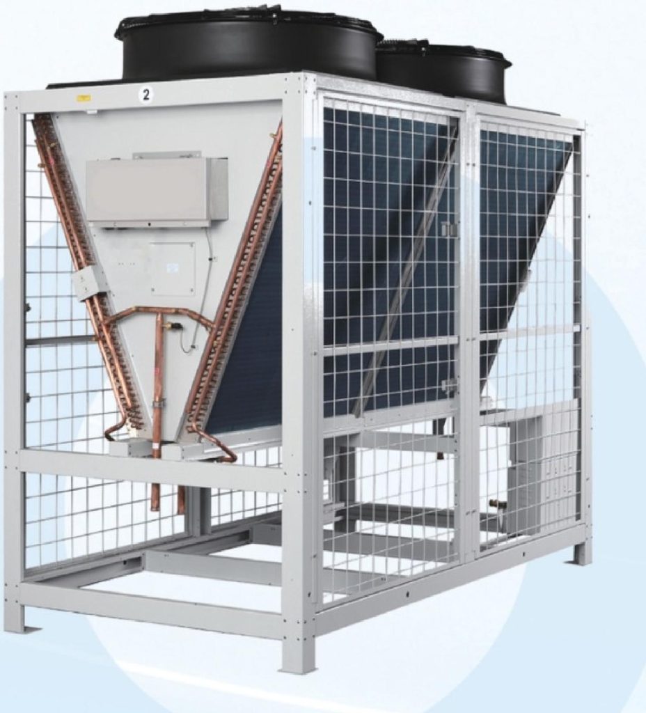
Centralized Outdoor Unit

FCV042SA · FCV050SA · FCV070SA · FCV080SA · FCV085SA

Centralized Outdoor Unit

The centralized outdoor unit uses modular combinations to accurately meet different cooling-capacity requirements, with high flexibility and scalability.

Discuss this product
Features & technical specifications4 specification tables

Product features

  • Modular combinations accurately match different cooling capacity requirements, with high flexibility and scalability.
  • An integrated Refrigerant Pump free-cooling design is available, providing a highly integrated system and up to 60% footprint savings.
  • The compact base module accommodates access requirements and simplifies transportation and installation.
  • Fan motors require very little maintenance and suit a range of climatic conditions.
Centralized outdoor unit — specifications
ParameterFCV042SAFCV050SAFCV070SAFCV080SAFCV085SA
Main power supply220V 1ph 50Hz380V 3ph 50Hz380V 3ph 50Hz380V 3ph 50Hz380V 3ph 50Hz
Condenser heat-rejection capacity (kW)44.553.071.579.586.0
Outdoor fan performance
ParameterFCV042SAFCV050SAFCV070SAFCV080SAFCV085SA
Airflow (m³/h)950016000188002000022000
Fan quantity11111
Noise, sound pressure level [dB(A)]5659606162
Dimensions and weight
ParameterFCV042SAFCV050SAFCV070SAFCV080SAFCV085SA
Length (mm)8801160116011601160
Depth (mm)9801225122512251225
Height (mm)14401700202020202020
Weight (kg)150208225225240
Recommended circuit breakers and cables
ParameterFCV042SAFCV050SAFCV070SAFCV080SAFCV085SA
Circuit breaker (A)1P-10A3P-10A3P-10A3P-10A3P-10A
Cable specifications (mm²)3*1.54*1.5; 2*0.54*1.5; 2*0.54*1.5; 2*0.54*1.5; 2*0.5

Reference conditions & selection notes

  • Condenser heat-rejection capacity is determined at an outdoor ambient temperature of 35°C and a condensing-to-ambient temperature difference of 15°C.
  • Airflow is at least the rated value and is adjustable.
  • Noise values are sound pressure levels measured at rated voltage and rated power using the method specified in JB/T4330.

Precision Air Conditioning Manual, pp. 10–11

Integrated Refrigerant Pump Centralized Outdoor Unit

CAVR42AP · CAVR50AP · CAVR70AP · CAVR80EP · CAVR85EP

Integrated Refrigerant Pump Centralized Outdoor Unit

The integrated fluorine-pump centralized outdoor unit is presented in the product manual as a dedicated outdoor-unit series with integrated fluorine-pump natural cooling.

Discuss this product
Features & technical specifications4 specification tables

Product features

  • Modular combinations accurately match different cooling capacity requirements, with high flexibility and scalability.
  • An integrated Refrigerant Pump free-cooling design is available, providing a highly integrated system and up to 60% footprint savings.
  • The compact base module accommodates access requirements and simplifies transportation and installation.
  • Fan motors require very little maintenance and suit a range of climatic conditions.
Integrated Refrigerant Pump centralized outdoor unit — specifications
ParameterCAVR42APCAVR50APCAVR70APCAVR80EPCAVR85EP
Main power supply220V 1ph 50Hz380V 3ph 50Hz380V 3ph 50Hz380V 3ph 50Hz380V 3ph 50Hz
Condenser heat-rejection capacity (kW)44.553.071.579.586.0
Outdoor fan performance
ParameterCAVR42APCAVR50APCAVR70APCAVR80EPCAVR85EP
Airflow (m³/h)950016000188002000022000
Fan quantity11111
Noise, sound pressure level [dB(A)]5659606162
Dimensions and weight
ParameterCAVR42APCAVR50APCAVR70APCAVR80EPCAVR85EP
Length (mm)8801160116011601160
Depth (mm)9801225122512251225
Height (mm)14401700202020202020
Weight (kg)180238255275300
Recommended circuit breakers and cables
ParameterCAVR42APCAVR50APCAVR70APCAVR80EPCAVR85EP
Circuit breaker (A)1P-10A3P-10A3P-10A3P-10A3P-10A
Cable specifications (mm²)3*1.5; 4*2.5; 2*0.54*1.5; 4*2.5; (2*0.5)X24*1.5; 4*2.5; (2*0.5)X24*1.5; 4*2.5; (2*0.5)X24*1.5; 4*2.5; (2*0.5)X2

Reference conditions & selection notes

  • Condenser heat-rejection capacity is determined at an outdoor ambient temperature of 35°C and a condensing-to-ambient temperature difference of 15°C.
  • Airflow is at least the rated value and is adjustable.
  • Noise values are sound pressure levels measured at rated voltage and rated power using the method specified in JB/T4330.

Precision Air Conditioning Manual, p. 12

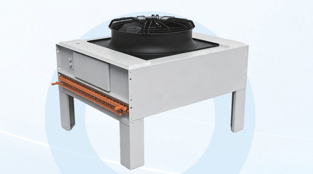
Flat Outdoor Unit

FCM028SA · FCM038SA · FCM042SA · FCM056SA · FCM070SA · FCM084SA

Flat Outdoor Unit

The flat outdoor unit uses an ultra-thin design to save outdoor floor area and is available with an optional integrated fluorine-pump natural-cooling solution.

Discuss this product
Features & technical specifications3 specification tables

Product features

  • Stepless variable-speed inverter fan.
  • An integrated Refrigerant Pump free-cooling solution is optional.
  • An ultra-thin design saves outdoor installation space.
  • Fan motors require very little maintenance and suit a range of climatic conditions.
Flat outdoor unit specifications
ParameterFCM028SAFCM038SAFCM042SAFCM056SAFCM070SAFCM084SA
Main power supply380V 3ph 50Hz380V 3ph 50Hz380V 3ph 50Hz380V 3ph 50Hz380V 3ph 50Hz380V 3ph 50Hz
Condenser heat-rejection capacity (kW)283854.062.070.084
Outdoor fan performance
ParameterFCM028SAFCM038SAFCM042SAFCM056SAFCM070SAFCM084SA
Airflow (m³/h)80001700017000150002000034000
Fan quantity111212
Noise, sound pressure level [dB(A)]585960616264
Dimensions (vertical discharge), weight and cables
ParameterFCM028SAFCM038SAFCM042SAFCM056SAFCM070SAFCM084SA
Length L (mm)107013701565156515652065
Depth W (mm)9909901275127512751275
Height H (mm)122012201275127513001275
Weight (kg)7685135140145240
Outdoor cable specification (mm²)4*1.54*1.54*1.54*2.54*2.54*2.5

Reference conditions & selection notes

  • Condenser heat-rejection capacity is determined at an outdoor ambient temperature of 35°C and a condensing-to-ambient temperature difference of 15°C.
  • Airflow is at least the rated value and is adjustable.
  • Noise values are sound pressure levels measured at rated voltage and rated power using the method specified in JB/T4330.

Precision Air Conditioning Manual, pp. 13–14

02 / Liquid cooling solutions

A complete cooling chain.
Down to the cold plate.

Connect the cold source to the CDU, secondary pipework, manifolds and server cold plates. Distributed and centralized architectures support retrofit facilities, AI training clusters and high-density data centers.

01 / HEAT REJECTIONCold source

Cooling tower or dry cooler

02 / HEAT EXCHANGECDU

Temperature, flow and pressure control

03 / DISTRIBUTIONPipework & manifold

Primary and secondary circuits

04 / SERVER COOLINGCold plate

Connectors and hose assemblies

Air and liquid work together

In the reference cold-plate architecture, liquid removes 50–90% of server heat. Air cooling handles the remaining 10–50% through room cooling, an air wall or a liquid-cooled rear door. The split depends on the server design.

Define the server interface first

Confirm the inlet temperature range, flow, pressure drop, fluid compatibility and connector specification. These determine the CDU, cold source and distribution network.

Cooling capacity and PUE depend on architecture, ambient conditions and the IT load. Reference figures and operating conditions are listed with the relevant equipment.

CDUs, cabinets, components, cold sources, pipework and controls

Row-level CDU

CDU-300LL3S · CDU-600LL3S · CDU-300LL3D · CDU-600LL3D

Row-level CDU

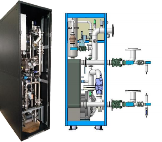
The row-level CDU is a large centralized cooling unit installed side-by-side with server cabinets. It mainly consists of a cabinet, plate heat exchanger, secondary-side circulating water pump, constant-pressure liquid replenishment system, expansion tank, filters, valves, sensors, control system, display screen and power supply module. Through the plate heat exchanger, cooled liquid is sent to the heat source to absorb heat, and the heat-carrying liquid then re-enters the plate heat exchanger for heat exchange treatment, forming a circulating heat exchange process.

Discuss this product
Features & technical specifications1 specification table

Product features

  • Dual power supply backup
  • High-efficiency variable-frequency single pump or dual pump optional
  • Anti-condensation control
  • Optional 50μm ultra-fine filtration unit
  • Automatic liquid replenishment system
  • Online maintenance
  • Intelligent group control
  • Corrosion-resistant stainless steel piping
  • Intelligent monitoring system
  • Online water quality monitoring
  • 10%–100% adjustable flow rate
  • Overpressure protection
  • Low energy consumption design
  • Leakage detection function
  • 10-inch color display screen
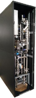
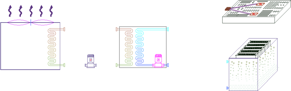
CDU internal equipment arrangement and heat-exchange circuit.
Row-level CDU model specifications
MODELCDU-300LL3SCDU-600LL3SCDU-300LL3DCDU-600LL3D
Rated heat exchange capacity (kW)300600300600
Unit rated flow rate (L/min)470860470860
Pump typeSingle pumpSingle pumpDual pumpDual pump
Primary supply/return water temperature (°C)35/4535/4535/4535/45
Primary working fluidSoftened water, PG25 aqueous solution, EG25 aqueous solutionSoftened water, PG25 aqueous solution, EG25 aqueous solutionSoftened water, PG25 aqueous solution, EG25 aqueous solutionSoftened water, PG25 aqueous solution, EG25 aqueous solution
Secondary supply/return water temperature (°C)40/5040/5040/5040/50
Secondary working fluidPG25 aqueous solution, EG25 aqueous solutionPG25 aqueous solution, EG25 aqueous solutionPG25 aqueous solution, EG25 aqueous solutionPG25 aqueous solution, EG25 aqueous solution
Dimensions W × D × H (mm)600*1200*2200600*1400*2200600*1200*2200900*1400*2200
Power supply specifications2-way 3Ph AC380-415V 50Hz2-way 3Ph AC380-415V 50Hz2-way 3Ph AC380-415V 50Hz2-way 3Ph AC380-415V 50Hz
Dual power input (optional)Mains / UPS / Diesel generator power supplyMains / UPS / Diesel generator power supplyMains / UPS / Diesel generator power supplyMains / UPS / Diesel generator power supply
Storage environment temperature and humidity-45 ~ 85℃; long-term 5%~85% non-condensing, short-term 5%~95% non-condensing-45 ~ 85℃; long-term 5%~85% non-condensing, short-term 5%~95% non-condensing-45 ~ 85℃; long-term 5%~85% non-condensing, short-term 5%~95% non-condensing-45 ~ 85℃; long-term 5%~85% non-condensing, short-term 5%~95% non-condensing
Altitude3000m (above 3000m, derated; for every 200m increase in altitude, ambient temperature rating decreases by 1.5℃)3000m (above 3000m, derated; for every 200m increase in altitude, ambient temperature rating decreases by 1.5℃)3000m (above 3000m, derated; for every 200m increase in altitude, ambient temperature rating decreases by 1.5℃)3000m (above 3000m, derated; for every 200m increase in altitude, ambient temperature rating decreases by 1.5℃)

Applications

High-density data centers · Retrofit and new-build data centers · Intelligent computing centers · Large-scale computer rooms · AI training clusters · High-power industrial equipment cooling · Scientific research laboratories

Reference conditions & selection notes

  • The source states that the above ratings are based on pure water as the working medium. Confirm cooling capacity and fluid requirements with technical personnel; the matrix also lists glycol options.
  • Storage humidity values are non-condensing. Above 3000 m, the ambient temperature rating decreases by 1.5°C for each additional 200 m.

Liquid Cooling Manual, pp. 1–2

Room-level CDU

CDU-900LF3S/D · CDU-1200LF3S/D · CDU-1800LF3S/D

Room-level CDU

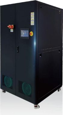
Room-level CDU is a large centralized cooling unit installed separately in the air-conditioned room. It mainly consists of a cabinet, plate heat exchanger, secondary-side circulating water pump, constant-pressure liquid replenishment system, expansion tank, filters, valves, sensors, control system, display screen and power supply module. Through heat exchange via the plate heat exchanger, cooled liquid is sent to the heat source to absorb heat, and the heat-carrying liquid then re-enters the plate heat exchanger for heat exchange treatment, forming a circulating heat exchange process.

Discuss this product
Features & technical specifications1 specification table

Product features

  • Year-round free cooling capability, subject to the cold-source and operating conditions.
  • Redundant key components; anti-condensation; circulating-pump and valve self-holding; dual power supply with uninterrupted switching; liquid leakage detection.
  • Differential-pressure, flow-rate, cold-standby, hot-standby, standalone, group-control, local and remote modes; multiple units can network automatically for group management.
  • Supports mixed CPU and GPU cold-plate liquid cooling and optional standard functional modules.
  • Stepless regulation over a wide cooling-capacity and differential-pressure adjustment range.
  • Optional inlet/outlet pipe directions, filtration grades and communication protocols.
  • High-head, large-flow functionality suitable for large ring networks.
  • Internal layout for maintenance access and online automatic liquid replenishment.
  • Sanitary-grade piping with high-precision filtration.
  • RS485 serial and RJ45 Ethernet ports; Modbus, TCP and UDP protocols.
Room-level CDU model specifications
MODELCDU-900LF3S/DCDU-1200LF3S/DCDU-1800LF3S/D
Rated heat exchange capacity (kW)90012001800
Unit rated flow rate (L/min)133017202400
Pump typeSingle pump / Dual pumpSingle pump / Dual pumpSingle pump / Dual pump
Primary supply/return fluid temperature (°C)35/4535/4535/45
Primary working fluidSoftened water, PG25 aqueous solution, EG25 aqueous solutionSoftened water, PG25 aqueous solution, EG25 aqueous solutionSoftened water, PG25 aqueous solution, EG25 aqueous solution
Secondary supply/return fluid temperature (°C)40/5040/5040/50
Secondary working fluidSoftened water, PG25 aqueous solution, EG25 aqueous solutionSoftened water, PG25 aqueous solution, EG25 aqueous solutionSoftened water, PG25 aqueous solution, EG25 aqueous solution
Dimensions W × D × H (mm)950x1500x22001200x1800x22001200x2000x2200
Power supply specificationsPower supply: 2-way 3Ph AC380-415V 50HzPower supply: 2-way 3Ph AC380-415V 50HzPower supply: 2-way 3Ph AC380-415V 50Hz
Dual power input (optional)Supported power sources: Mains / UPS / Diesel generatorSupported power sources: Mains / UPS / Diesel generatorSupported power sources: Mains / UPS / Diesel generator
Storage environment temperature and humidityStorage environment temperature and humidity: -45~85℃; 5%~85% RH non-condensing (long-term), 5%~95% RH non-condensing (short-term)Storage environment temperature and humidity: -45~85℃; 5%~85% RH non-condensing (long-term), 5%~95% RH non-condensing (short-term)Storage environment temperature and humidity: -45~85℃; 5%~85% RH non-condensing (long-term), 5%~95% RH non-condensing (short-term)
AltitudeAltitude: 3000m (derated above 3000m; ambient temperature rating decreases by1.5℃ for every 200m increase in altitude)Altitude: 3000m (derated above 3000m; ambient temperature rating decreases by1.5℃ for every 200m increase in altitude)Altitude: 3000m (derated above 3000m; ambient temperature rating decreases by1.5℃ for every 200m increase in altitude)

Applications

High-density data centers · Retrofit and new-build data centers · Intelligent computing centers · Large-scale computer rooms · AI training clusters · High-power industrial equipment cooling · Scientific research laboratories

Reference conditions & selection notes

  • Verify ratings for the selected coolant and operating conditions. Storage humidity is non-condensing; altitude derating applies above 3000 m at 1.5°C per additional 200 m.

Liquid Cooling Manual, p. 3

Rack-mounted Liquid-to-Liquid CDU

Rack-mounted / liquid-to-liquid

Rack-mounted Liquid-to-Liquid CDU

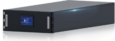
The rack-mounted liquid-to-liquid CDU is a core liquid cooling device designed specifically for high power density cabinets in data centers. It consists of modules such as the heat dissipation module, pump drive module, voltage stabilization module, control module and power supply module. Through heat exchange via the plate heat exchanger, cooled liquid is sent to the heat source to absorb heat, and the heat-carrying liquid then re-enters the plate heat exchanger for heat exchange treatment.

Discuss this product
Features & technical specifications1 specification table

Product features

  • Standard 4U rack-mount chassis
  • All stainless steel piping
  • High-efficiency centrifugal pumps with automatic flow adjustment
  • Redundant pump drivers with 1+1 cold standby
  • Active anti-condensation function
  • 7-inch LCD control screen
  • Built-in leakage detection and automatic liquid replenishment
  • Constant differential-pressure or constant-flow output
  • Integrated temperature, pressure, leakage and humidity monitoring
  • Dual power supply
  • Modbus RTU and TCP/IP support
Rack-mounted liquid-to-liquid configuration
ParameterSource specification
ChassisStandard 4U rack mount
PipingAll stainless steel
PumpHigh-efficiency centrifugal; flow adapts to terminal-device quantity
Pump-driver redundancy1+1 cold standby
Display7-inch LCD
Automatic output controlConstant differential pressure or constant flow
MonitoringTemperature, pressure, leakage, ambient temperature and humidity
Protection and make-upActive anti-condensation, built-in leakage detection and automatic liquid replenishment
PowerDual power supply
CommunicationModbus RTU and TCP/IP

Applications

High-density data centers · Retrofit and new-build data centers · Intelligent computing centers · Large-scale computer rooms · AI training clusters · High-power industrial equipment cooling · Scientific research laboratories

Reference conditions & selection notes

  • The source does not unambiguously attach a model-specific rating matrix to this 4U product. The large CDU-900LF3S/D through CDU-1800LF3S/D table is preserved with the room-level CDU; slide 4 contains a separate, inconsistently labeled reference table.

Liquid Cooling Manual, p. 3 (rack-mounted liquid-to-liquid description)

Rack-mounted Air-to-Liquid CDU

Rack-mounted / air-to-liquid

Rack-mounted Air-to-Liquid CDU

The rack-mounted air-to-liquid CDU is a high-density liquid cooling server heat dissipation solution developed specifically for the data center industry, addressing the sensitivity of server CPU and GPU heat generation to ambient temperature. It consists of water pumps, heat exchangers, fans, filters, expansion tanks and control modules. The built-in circulating pump provides power for water circulation, carrying away heat from liquid-cooled servers, which is then dissipated into the environment by the fans.

Discuss this product
Features & technical specifications1 specification table

Product features

  • Standard 10U rack-mount chassis
  • All stainless steel piping
  • High-efficiency centrifugal pumps with automatic flow adjustment
  • Redundant pump drivers with 1+1 cold standby
  • Active anti-condensation function
  • 4.3-inch LCD control screen
  • Built-in leakage detection and automatic liquid replenishment
  • Constant differential-pressure or constant-flow output
  • Integrated monitoring
  • Dual power supply
  • Modbus RTU and TCP/IP support
CDU-35LJ / CDU-80LJ / CDU-100LJ — source reference table
MODELCDU-35LJCDU-80LJCDU-100LJ
Heat exchange capacity (kW)3580100
Primary supply/return fluid temperature (°C)35/4535/4535/45
Primary working fluidSoftened waterSoftened waterSoftened water
Secondary supply/return fluid temperature (°C)40/5040/5040/50
Secondary working fluidPG25PG25PG25
Secondary side filtration precision100μm100μm100μm
Primary side connection type1.5" tri-clamp1.5" tri-clamp1.5" tri-clamp
Secondary side connection type1.5" tri-clamp1.5" tri-clamp1.5" tri-clamp
Circulating pump quantityDual pumpsDual pumpsDual pumps
Dimensions W × L × H (mm)481*950*171.5481*851*174481*851*174
Power supply specifications220VAC48VDC48VDC

Applications

High-density data centers · Retrofit and new-build data centers · Intelligent computing centers · Large-scale computer rooms · AI training clusters · High-power industrial equipment cooling · Scientific research laboratories

Reference conditions & selection notes

  • Slide 4 labels the product Air-to-Liquid, but its CDU-35LJ / CDU-80LJ / CDU-100LJ reference table specifies both primary and secondary liquid circuits, while the description specifies fan heat rejection. These values are transcribed as reference data and are not verified air-to-liquid product ratings. Confirm the model, thermal interface and dimensions before selection.
  • The air-to-liquid description specifies a standard 10U chassis, a 4.3-inch LCD and fan heat rejection. These differ from the 171.5–174 mm heights in the reference table.
  • The source table labels dimensions W × L × H; that dimension order is retained. PG25 is retained as the source fluid designation.

Liquid Cooling Manual, p. 4

Cabinet-mounted Air-to-Liquid CDU

CDU-16AJ · CDU-120AL3SS61222

Cabinet-mounted Air-to-Liquid CDU

Cabinet-mounted Air-to-Liquid CDU is designed specifically for high heat density liquid-cooled server application scenarios. It requires no external cooling water supply or overhead cabling via raised floor systems. The overall cooling system layout is simple, with a short installation cycle and easy operation and maintenance. It is particularly suitable for retrofitting traditional air-cooled data centers and small high-performance computing centers.

How it works

The cabinet-mounted air-to-liquid CDU consists of rear fans, high-efficiency air-to-liquid heat exchangers, water pumps, controllers and pipeline components. Driven by the water pump, high-temperature working fluid from liquid-cooled servers undergoes convective heat exchange with cold air in the data room. After cooling, the fluid returns to the liquid-cooled servers to complete the heat exchange cycle.

Discuss this product
Features & technical specifications2 specification tables

Product features

  • Single-cabinet heat exchange capacity up to 120 kW
  • Rapid deployment
  • Two high-performance water pumps
  • Integrated control system supporting mainstream communication protocols
  • N+1 high-efficiency hot-swappable fans
  • Total power consumption below 5% of heat load
  • Compatible with existing hot and cold aisle layouts
CDU-16AJ model specifications
MODELCDU-16AJ
Heat exchange capacity (kW)16
Primary side inlet air temperature (°C)25
Air volume (m³/h)2700
Secondary side liquid supply temperature (°C)40
Secondary side working fluidPG25
Secondary side flow rate (L/min)25
Secondary side filtration precision100μm
Secondary side connection type1.5" tri-clamp
Circulating pump quantityDual pumps
Dimensions W × D × H (mm)482*857*443
Power supply specifications220V/50Hz
CDU-120AL3SS61222 model specifications
MODELCDU-120AL3SS61222
Heat exchange capacity (kW)120
Primary air inlet temperature (°C)24
Airflow rate (m³/h)15000
Secondary fluid inlet temperature (°C)≤ 45
Secondary filtration precision (mesh)100
Secondary interface sizeDN50
Circulating pump quantity2
Dimensions W × D × H (mm)600*1200*2200
Power supply specifications380V/50Hz
Power consumption (kW)<5

Reference conditions & selection notes

  • Both model tables appear on slide 5 with the cabinet-mounted air-to-liquid description. They are preserved separately; the source does not explicitly map every cabinet feature to both models.
  • Cooling capacity depends on working conditions. Confirm the selected working conditions and cooling medium with technical personnel.
  • CDU-16AJ filtration is 100 μm; CDU-120AL3SS61222 filtration is 100 mesh. These are different source units and are not interchangeable.
  • The 120 kW model lists <5 kW consumption; the description separately states total power below 5% of the heat load. These apply to the specified operating point, not every load.

Liquid Cooling Manual, p. 5

Liquid-cooled Cabinet

HD9000 Series

Liquid-cooled Cabinet

A liquid-cooled cabinet is a high-density server cabinet that replaces traditional air cooling with liquid cooling media. It mainly consists of the cabinet, manifold, power distribution system and internal equipment. As the carrier for liquid-cooled devices, each node device is connected to the liquid cooling system via hydraulic hoses to ensure effective heat dissipation.

Discuss this product
Features & technical specifications2 specification tables

Product features

  • 1.2–2.0 mm high-quality cold-rolled steel plates
  • Static load capacity over 1500 kg
  • Single U-layer board load capacity of at least 50 kg
  • Welded or assembled reinforced frame
  • Adjustable feet and universal casters
  • Quick-detachable side and rear doors
  • Upper cable routing and lower pipe routing
  • Dual power supply, leakage alarm and drip tray
HD9000 liquid-cooled cabinet model dimensions
ModelWidth W (mm)Depth L (mm)Height H (mm)Available space
HD9000-Y61220600mm1200mm2000mm42U
HD9000-Y61222600mm1200mm2200mm47U
HD9000-Y61420600mm1400mm2000mm42U
HD9000-Y61422600mm1400mm2200mm47U
System hand-off interfaces
InterfaceSource-defined scope
1Chilled-water source + liquid-cooling CDU + pipe network, provided with the complete liquid-cooled cabinet
2Chilled-water source + liquid-cooling CDU + pipe network + distribution unit, with server quick connectors and hoses

Reference conditions & selection notes

  • The source describes water and fluorinated liquid as examples of cooling media. Actual fluid compatibility must be selected for the server, hoses, connectors and CDU.
  • Slide 28 shows a layout with liquid-cooled cabinets, CDUs and in-row air conditioners; the two interfaces define different equipment supply boundaries.

Liquid Cooling Manual, pp. 6 and 28

Manifold

MF-DS · MF-BS

Manifold

The manifold is a water distribution and collection header for server liquid cooling, connecting the CDU to the cold plates of rack-mounted servers. It is available in quick-disconnect and blind-mate versions. It can be integrated into or externally connected to the cabinet frame, with branch flow selected according to server heat dissipation requirements.

Discuss this product
Features & technical specifications2 specification tables

Product features

  • 304 stainless-steel main body, air vent and related components; EPDM hoses for corrosion resistance.
  • Pipeline design targets branch-flow non-uniformity below 10%.
  • Customized for server layout and multiple cabinet mounting methods.
  • In-cabinet installation operable by one person.
  • Server branch connectors use drip-free quick connections for installation and maintenance.
  • Deionized-water rinsing, high-temperature gas drying and transport under 1.5 bar gas pressure for cleanliness.
MF-DS / MF-BS model matrix
Model familySquare-section specification (source notation)Branch configurationMaterialConnectionApplicable fluid
MF-DS*30 × 30Customizable; standard 16 inlet + 16 outletSUS304 / SUS316LQuick-disconnectEthylene glycol solution, propylene glycol solution, deionized water
MF-DS*40 × 40Customizable; standard 16 inlet + 16 outletSUS304 / SUS316LQuick-disconnectEthylene glycol solution, propylene glycol solution, deionized water
MF-DS*50 × 50Customizable; standard 16 inlet + 16 outletSUS304 / SUS316LQuick-disconnectEthylene glycol solution, propylene glycol solution, deionized water
MF-BS*30 × 30Customizable; standard 16 inlet + 16 outletSUS304 / SUS316LBlind-mateEthylene glycol solution, propylene glycol solution, deionized water
MF-BS*40 × 40Customizable; standard 16 inlet + 16 outletSUS304 / SUS316LBlind-mateEthylene glycol solution, propylene glycol solution, deionized water
MF-BS*50 × 50Customizable; standard 16 inlet + 16 outletSUS304 / SUS316LBlind-mateEthylene glycol solution, propylene glycol solution, deionized water
Distribution-unit engineering guidance
ParameterTypical source guidance
Server typesRack-mounted liquid-cooled servers and blade liquid-cooled servers
Internal pipeworkStainless steel; sanitary clamp connections
InstallationIntegrated into or externally connected to the cabinet frame
Branch flow1–4 L/min, based on server heat-dissipation requirements
Branch port diameterTypically 3–6 mm, with matched quick connectors
Quick connector materialTypically stainless steel or aluminum
Example connector brandsStaubli, Parker, CPC
Air removal / drainageAutomatic air vent and drain
Branch regulationNo branch flow or temperature control
Typical fabricationConstant-diameter stainless-steel square tubing
Typical branch count20 branches, supporting 20 servers per cabinet
Distribution arrangementTypically one unit per cabinet; single server inlet and outlet
Branch connectionsExternal threads; end caps applied at factory; G1/8 common according to server interface
MountingGenerally at cabinet rear door, separate from PDU
Typical outer dimensionApproximately 33 × 33 mm

Reference conditions & selection notes

  • Slide 7 places branch configuration under the printed Material column and material under Number of Branches; the table above uses labels matching the actual cell content. Its printed Working Pressure column contains fluid names; no numeric working pressure is supplied.
  • The slide 7 model series has standard 16-inlet/16-outlet configuration; slides 29–30 give separate typical engineering guidance of 20 branches. The typical guidance is not a rating for every MF model.
  • The 30 × 30 / 40 × 40 / 50 × 50 source table does not print a dimension unit. The 33 × 33 mm example comes from slide 30.

Liquid Cooling Manual, pp. 6–7 and 29–30

Liquid Cooling Ring Piping

Prefabricated Ring Distribution Piping

Liquid Cooling Ring Piping

The ring distribution piping is a modular prefabricated piping system consisting of ring-shaped supply and return main pipelines, branch pipelines connecting manifolds and CDUs, valves, automatic air vents, pipe supports, drip trays and water leakage detection systems. It connects to the secondary water circuit and allows branch flow to be controlled through valves.

Discuss this product
Features & technical specifications1 specification table

Product features

  • Factory-prefabricated engineering-free design
  • Transported under nitrogen pressure
  • Rapid on-site assembly
  • Ring-network redundancy with isolation valves
  • Hygienic-grade 304 stainless steel piping
  • Automatic high-point steam-water separation and exhaust
  • Low-point blowdown and emergency discharge ports
  • One-meter-level water-leak positioning and remote alarms
Ring-piping reference configuration
ComponentQuantitySpecification
Ring-network main pipeline19343 × 913 × DN125
Main-pipeline valves38DN125 butterfly valve
Ring-network branch pipeline321.5 inch, L=1500
Branch-pipeline valves321.5 inch butterfly valve
Primary-side pipeline62.5 inch, L=2500
Primary-side pipeline valves62.5 inch butterfly valve
Secondary-side pipeline62.5 inch, L=1500
Secondary-side pipeline valves61.5 inch butterfly valve
Liquid tray19428 × 1020 × 40
Pipe supports16H=200
Water immersion sensor1Not specified
Water-leak detection cable145 m

Reference conditions & selection notes

  • The source reference aisle contains 3 liquid-cooling CDUs, 7 chilled-water air conditioners, 16 liquid-cooled cabinets and 4 network cabinets. This bill of materials describes that layout, not a universal installation.
  • The source does not explicitly print units for every geometric value (9343 × 913, L=1500/2500, tray 9428 × 1020 × 40 and H=200). The values are retained without assigning unprinted units.
  • The source lists 2.5-inch secondary pipework with 1.5-inch secondary valves. This difference is retained for technical confirmation.
  • A positioning leak-detection cable at the lower ring-network area provides approximately 1 m positioning granularity. Alarms can upload to the environmental-monitoring system and platform.

Liquid Cooling Manual, p. 7

Liquid-Cooled Door

Active Type · Passive Type

Liquid-Cooled Door

Installed at the cabinet rear or front to enhance server airflow, the liquid-cooled door can combine with cold-plate cooling for a fully liquid-cooled cabinet. It is intended for high cabinet heat loads and equipment sensitive to ambient temperature. The active rear-door version comprises a heat exchanger, fan wall and sheet-metal components; the passive version comprises a heat exchanger and perforated door.

Discuss this product
Features & technical specifications1 specification table

Product features

  • Self-diagnosis and on-site diagnosis
  • Safety protection and leakage detection
  • HMI displaying alarm information
  • Standard quick couplings
  • Bottom casters for door movement and rapid deployment
  • Modular design for different data-center scales and layouts
Active and passive liquid-cooled door specifications
ParameterActive TypePassive Type
Power supplyAC220VDC48V
Output CapacityCooling Capacity:20kW @AT=2.7℃, 130L/minCooling Capacity:10.1kW @AT=2.6℃, 55L/min
Water-side supply / return temperature32/34.2℃32/34.7℃
Air-side inlet / outlet temperature45℃/34.7℃40℃/34.6℃
Water Flow Rate130L/min55L/min
Airflow Rate6300 m³/h5950 m³/h
Liquid-Cooled Door Water-Side Pressure Drop74.2KPa43KPa
Power consumption1.1kW30W
Dimensions W × D × H595×250×2250 mm599.5*150*2195mm
Net / operating weight105kg/115kg71.5kg/91.5kg
Compatible cabinet W × D × H600*1200*2250mm600×1200×2200mm

Applications

High-density data centers · Edge computing nodes · Special industry scenarios · Legacy data center renovation scenarios

Reference conditions & selection notes

  • Capacity is stated at the individual source duty points: active 20 kW at AT=2.7°C and 130 L/min; passive 10.1 kW at AT=2.6°C and 55 L/min. The source does not define AT, so it is not relabeled as another temperature difference.
  • The water temperatures, airflow, pressure drops, power, dimensions and compatible cabinet dimensions are separate for active and passive versions.
  • Slide 20 shows cold plate + liquid-cooled rear door as an all-liquid architecture option. Compressor-free operation depends on cold-source conditions and permissible cabinet inlet-air temperature.

Liquid Cooling Manual, p. 8

Quick Connectors

UQD Series · UQDB Series

Quick Connectors

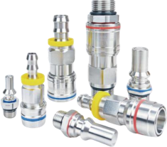
Quick connectors are connecting components between devices in liquid cooling circulation systems. They enable quick connection and disconnection, ensuring no leakage while reducing draining and filling operations. They can be freely plugged and unplugged under pressure.

Discuss this product
Features & technical specifications2 specification tables

Product features

  • Push-to-connect, self-locking and blind-mate connector versions.
  • Sealing tests; double shut-off flat valves for high flow and reduced spillage.
  • Drip-free connection and disconnection, including under-pressure operation as described in the source.
  • Single-handed push-to-connect operation.
  • Designed according to OCP UQD specifications; the source also states compliance with OCP performance standards.
  • Multiple port sizes and end connections; ORB and BSPP male ends and barb female ends are described.
UQD plug and socket model matrix
Connector typeModelEquivalent port sizeConnection portShared material / pressure / fluid specification
UQD PlugUQD02P-1SMG012NDN03G1/8 external threadSUS316 body; EPDM seals; working pressure 2 MPa; deionized water, purified water, ethylene glycol aqueous solution, propylene glycol aqueous solution, fluorinated liquid
UQD PlugUQD02P-1SMU042NDN037/16-20 UNF external threadSUS316 body; EPDM seals; working pressure 2 MPa; deionized water, purified water, ethylene glycol aqueous solution, propylene glycol aqueous solution, fluorinated liquid
UQD PlugUQD04P-1SMG022NDN05G1/4 external threadSUS316 body; EPDM seals; working pressure 2 MPa; deionized water, purified water, ethylene glycol aqueous solution, propylene glycol aqueous solution, fluorinated liquid
UQD PlugUQD04P-1SMU062NDN059/16-18 UNF external threadSUS316 body; EPDM seals; working pressure 2 MPa; deionized water, purified water, ethylene glycol aqueous solution, propylene glycol aqueous solution, fluorinated liquid
UQD PlugUQD06P-1SMG042NDN07G3/8 external threadSUS316 body; EPDM seals; working pressure 2 MPa; deionized water, purified water, ethylene glycol aqueous solution, propylene glycol aqueous solution, fluorinated liquid
UQD PlugUQD06P-1SMU082NDN073/4-16 UNF external threadSUS316 body; EPDM seals; working pressure 2 MPa; deionized water, purified water, ethylene glycol aqueous solution, propylene glycol aqueous solution, fluorinated liquid
UQD PlugUQD08P-1SMU102NDN107/8-14 UNF external threadSUS316 body; EPDM seals; working pressure 2 MPa; deionized water, purified water, ethylene glycol aqueous solution, propylene glycol aqueous solution, fluorinated liquid
UQD PlugUQD08P-1SMG052NDN10G1/2 external threadSUS316 body; EPDM seals; working pressure 2 MPa; deionized water, purified water, ethylene glycol aqueous solution, propylene glycol aqueous solution, fluorinated liquid
UQD SocketUQD02S-1SFU042NDN037/16-20 UNF internal threadSUS316 body; EPDM seals; working pressure 2 MPa; deionized water, purified water, ethylene glycol aqueous solution, propylene glycol aqueous solution, fluorinated liquid
UQD SocketUQD02S-1SWP042NDN03Barb fitting for 1/4" ID hoseSUS316 body; EPDM seals; working pressure 2 MPa; deionized water, purified water, ethylene glycol aqueous solution, propylene glycol aqueous solution, fluorinated liquid
UQD SocketUQD04S-1SFU062NDN059/16-18 UNF internal threadSUS316 body; EPDM seals; working pressure 2 MPa; deionized water, purified water, ethylene glycol aqueous solution, propylene glycol aqueous solution, fluorinated liquid
UQD SocketUQD04S-1SWP062NDN05Barb fitting for 3/8" ID hoseSUS316 body; EPDM seals; working pressure 2 MPa; deionized water, purified water, ethylene glycol aqueous solution, propylene glycol aqueous solution, fluorinated liquid
UQD SocketUQD06S-1SFU082NDN073/4-16 UNF internal threadSUS316 body; EPDM seals; working pressure 2 MPa; deionized water, purified water, ethylene glycol aqueous solution, propylene glycol aqueous solution, fluorinated liquid
UQD SocketUQD06S-1SWP082NDN07Barb fitting for 1/2" ID hoseSUS316 body; EPDM seals; working pressure 2 MPa; deionized water, purified water, ethylene glycol aqueous solution, propylene glycol aqueous solution, fluorinated liquid
UQD SocketUQD08S-1SMU102NDN107/8-14 UNF external threadSUS316 body; EPDM seals; working pressure 2 MPa; deionized water, purified water, ethylene glycol aqueous solution, propylene glycol aqueous solution, fluorinated liquid
UQD SocketUQD08S-1SWP102NDN10Barb fitting for 5/8" ID hoseSUS316 body; EPDM seals; working pressure 2 MPa; deionized water, purified water, ethylene glycol aqueous solution, propylene glycol aqueous solution, fluorinated liquid
UQDB plug and socket model matrix
Connector typeModelEquivalent port sizeConnection portShared material / pressure / fluid specification
UQDB PlugUQDB02P-1SMU042NDN037/16-20 UNF External ThreadSUS316 body; EPDM seals; working pressure 2 MPa; deionized water, purified water, ethylene glycol aqueous solution, propylene glycol aqueous solution, fluorinated liquid
UQDB PlugUQDB04P-1SMU062NDN059/16-18 UNF External ThreadSUS316 body; EPDM seals; working pressure 2 MPa; deionized water, purified water, ethylene glycol aqueous solution, propylene glycol aqueous solution, fluorinated liquid
UQDB PlugUQDB06P-1SMU082NDN073/4-16 UNF External ThreadSUS316 body; EPDM seals; working pressure 2 MPa; deionized water, purified water, ethylene glycol aqueous solution, propylene glycol aqueous solution, fluorinated liquid
UQDB PlugUQDB08P-1SMU102NDN107/8-14 UNF External ThreadSUS316 body; EPDM seals; working pressure 2 MPa; deionized water, purified water, ethylene glycol aqueous solution, propylene glycol aqueous solution, fluorinated liquid
UQDB SocketUQDB02S-1SMU062NDN039/16-18 UNF External ThreadSUS316 body; EPDM seals; working pressure 2 MPa; deionized water, purified water, ethylene glycol aqueous solution, propylene glycol aqueous solution, fluorinated liquid
UQDB SocketUQDB04S-1SMU082NDN053/4-16 UNF External ThreadSUS316 body; EPDM seals; working pressure 2 MPa; deionized water, purified water, ethylene glycol aqueous solution, propylene glycol aqueous solution, fluorinated liquid
UQDB SocketUQDB06S-1SMU102NDN077/8-14 UNF External ThreadSUS316 body; EPDM seals; working pressure 2 MPa; deionized water, purified water, ethylene glycol aqueous solution, propylene glycol aqueous solution, fluorinated liquid
UQDB SocketUQDB08S-1SMU122NDN101 1/16-12 UNF External ThreadSUS316 body; EPDM seals; working pressure 2 MPa; deionized water, purified water, ethylene glycol aqueous solution, propylene glycol aqueous solution, fluorinated liquid

Reference conditions & selection notes

  • The source states OCP specification and performance compliance; no independent certification or test report is included in the presentation.
  • Model numbers, thread direction and exact thread sizes are retained individually, including UQD08S-1SMU102N external thread. Verify mating pairs, fluids and operating pressure before selection.

Liquid Cooling Manual, p. 9

Hydraulic Hose Assembly

006 Series

Hydraulic Hose Assembly

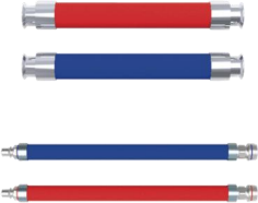
The hydraulic hose assembly is composed of crimped connectors and hydraulic hoses assembled through a specific process. It is used for flexible connections between liquid cooling manifolds and liquid-cooled servers, and between liquid cooling CDUs and manifolds. Crimped connectors can be threaded, flanged or custom elbow types.

Discuss this product
Features & technical specifications1 specification table

Product features

  • PTFE, EPDM and NBR hose materials optional
  • Self-sealing quick couplings, manually sealed ball valves and hose barbs optional
  • Female/female, male/male or mixed end configurations
  • Compatible with different cooling media
  • One-handed push-to-connect design
  • Red and blue inlet/outlet markings
006-series hose model matrix
Product codeSizeInner diameter (mm)Outer diameter (mm)Working pressure (unit not stated)Burst pressure (unit not stated)Minimum bend radius (mm)Unit weight (kg/m)Fixed length (m)
006-103/8"9.517.0200700700.23100
006-131/2"12.721.02007001000.32100
006-165/8"15.924.02007001200.4060
006-193/4"19.028.02007001500.4860
006-251"25.435.62007002000.7360
006-321-1/4"31.843.52007002501.0040
006-381-1/2"38.152.02008002301.3840
006-502"50.866.02008003001.9040
006-632-1/2"63.579.52008003802.5040
006-763"76.294.22008004603.4040

Reference conditions & selection notes

  • The slide gives working pressure 200 and burst pressure 700 or 800 without pressure units. These numbers are retained without conversion or an assumed bar/psi rating.
  • Minimum bend radius and fixed length are model-specific. Connector type, hose material and cooling-medium compatibility are selected for the assembly.

Liquid Cooling Manual, p. 10

Liquid Cooling Plate

Customized Cold Plate

Liquid Cooling Plate

Thermal grease is applied between the liquid cooling plate and the chip to conduct heat into the cold plate, which is then carried away by flowing liquid. The cold plate is used for CPUs, GPUs, memory modules and other components.

Discuss this product
Features & technical specifications1 specification table

Product features

  • Internal channels dissipate heat from chips through circulating liquid
  • Customizable shape and dimensions
  • Strict sealing, corrosion resistance and anti-leakage design
  • High heat dissipation power
  • Good temperature uniformity
  • Low thermal resistance and low flow resistance
  • Thermal simulation locates CPU and GPU heat sources to optimize channel design
Custom cold-plate design inputs
ItemSource description
Target componentsCPU, GPU, memory modules and other components
Heat transferThermal grease transfers chip heat to the cold plate; circulating liquid removes it
ConstructionInternal coolant channels; customizable plate shape and dimensions
Design criteriaSealing, corrosion resistance, leakage prevention, temperature uniformity, thermal resistance and flow resistance
SimulationCPU/GPU heat-source location used to optimize channel design

Reference conditions & selection notes

  • This is a customized product. The source supplies no fixed model dimensions, flow rate, pressure or model-specific heat rating.
  • The slide describes potential PUE and energy-use reductions, without a cold-plate-specific test condition or quantified rating.

Liquid Cooling Manual, p. 10

YW-BYC-120 Liquid Make-up Cart

YW-BYC-120

YW-BYC-120 Liquid Make-up Cart

This equipment is mainly used for constant-pressure liquid make-up in heat-dissipating cabinet systems, or for refilling liquid into make-up tanks and other containers that require liquid supplementation.

Discuss this product
Features & technical specifications1 specification table

Product features

  • Simple operation for efficient liquid replenishment
  • Large-capacity water tank for multiple refills
  • Flow switch for high reliability
  • Long-distance liquid replenishment
  • Bottom caster design
  • Suitable for high-flow rapid replenishment and ultra-low-flow daily replenishment
  • Simple and efficient operating interface; caster-equipped base with structural strength.
YW-BYC-120 make-up cart specifications
ParameterYW-BYC-120
Power supply type220VAC /1Ph50-60Hz
Rated current2.6A
Maximum power450W
Reserved wire length≥10m
Wiring methodIEC C13
Rated capacity100L
Maximum make-up flow rate≥50L/min
Applicable working fluid typesPropylene glycol solution / Ethylene glycol solution / Water + additives
Filter screen filtration precision100 mesh

Reference conditions & selection notes

  • YW-BYC-120 is the source model designation; the table gives rated tank capacity 100 L. The model suffix is not substituted for the tank rating.
  • The source states maximum make-up flow ≥50 L/min. Reserved cable length ≥10 m and IEC C13 wiring are included in the table.

Liquid Cooling Manual, p. 11

YW-JFZ-30 Liquid Cooling Dummy Load

YW-JFZ-30

YW-JFZ-30 Liquid Cooling Dummy Load

The liquid cooling dummy load simulates real electrical heating conditions. It can accurately simulate loads, and multi-level combinations can simulate different server heating states. It is used in data centers and communication rooms to test refrigeration-system performance and ensure stable equipment operation.

Discuss this product
Features & technical specifications1 specification table

Product features

  • Temperature-limited heating and over-pressure difference protection shutoff
  • Sanitary-grade pipelines with high-precision filtration
  • Accurate simulation of server flow resistance
  • Adjustable power and adaptable electrical interfaces
  • HMI displaying real-time operating parameters
  • Leakage detection
  • Water leakage, electric leakage, overtemperature, grounding and overpressure protection
  • Sealed without PTFE tape or sealant.
  • Overtemperature alarm at 80°C; electric-leakage protection to prevent short circuits.
YW-JFZ-30 dummy-load specifications
ParameterYW-JFZ-30
Rated heat exchange power30KW
Power supply220VAC /1Ph50-60Hz
Withstand pressure10bar
Air tightnessNo leakage for 2 hours at 1.2MPa
Insulation classClass F
Inlet liquid temperature range5℃-75℃
Dimensions483x262x827mm

Reference conditions & selection notes

  • The source distinguishes 10 bar withstand pressure from the air-tightness test: no leakage for 2 hours at 1.2 MPa.
  • The inlet-fluid range is 5–75°C; the safety description separately gives an 80°C overtemperature alarm.

Liquid Cooling Manual, p. 11

Cooling Tower

Open / Closed Type

Cooling Tower

Open or closed cooling towers use evaporative cooling to reject heat relative to the outdoor wet-bulb temperature. The source gives a 2–3°C approach, 27°C cooling water at 35°C dry-bulb / 24°C wet-bulb conditions, and 34.5°C cooling water at a 31.5°C wet-bulb condition. It cites secondary supply ≤36°C and 20 W/kW power per unit heat exchange for that example. Annual free-cooling suitability depends on local weather and the server liquid-temperature limit.

Discuss this product
Features & technical specifications4 specification tables
Primary-side cold-source selection
Climate / cooling requirementWater availabilityRecommended cold source
Low ambient temperature; year-round free cooling possibleAbundantClosed or open cooling tower
Low ambient temperature; year-round free cooling possibleScarceDry cooler
High ambient temperature; mechanical-cooling backup neededAbundantChiller + cooling tower + plate heat exchanger
High ambient temperature; mechanical-cooling backup neededScarceAir-cooled chiller
Primary / secondary temperature design guidance
Design parameterPrimary sideSecondary side
Supply temperatureRecommended ≤35°C, considering local weather and required secondary supply; W45 or W+ allowed where cooling requirements permitRecommended 40–48°C for energy efficiency; temperature and flow must meet liquid-cooled component requirements
Supply / return temperature difference6–10°C; ideal 8–10°C5–10°C; recommended ideal 6–8°C
Closed tower and evaporative dry cooler comparison
Comparison itemClosed cooling towerEvaporative dry cooler
Energy efficiencyRelatively superiorRelatively inferior
FootprintSmallLarge
CostLowHigh
Annual water consumptionApproximately 1.8–2.0 L/(kW·h)<0.5 L/(kW·h); varies by city
Peak 12-hour water usageRelatively highRelatively low
Suitable regionsAbundant water resourcesWater-scarce regions; strict WUE limits
Year-round waterless operationNot possibleNot possible; water needed during high outdoor temperatures, waterless operation possible at other times
Cooling-tower source operating example
ParameterSource value
TypeOpen or closed
Heat-rejection basisEvaporative / wet bulb
Approach Δt2–3°C
Reference ambient dry bulb / wet bulb35°C / 24°C
Reference cooling-water temperature27°C
High wet-bulb example31.5°C
Cooling water at high wet bulb34.5°C
Supported secondary liquid supply in example≤36°C
Power per unit heat exchange20 W/kW

Reference conditions & selection notes

  • Weather and water-temperature figures are source design examples, not universal performance guarantees. The secondary ≤36°C example on slide 21 differs from the 40–48°C efficiency guidance on slide 22 and applies to a different design discussion.
  • The water-use comparison on slide 23 specifically names closed cooling towers; its values are not assigned to every open tower.
  • W45 and W+ are retained as source designations; the presentation does not define those temperature classes further.

Liquid Cooling Manual, pp. 21–23

Evaporative Dry Cooler

Dry Cooler

Evaporative Dry Cooler

The dry cooler is intended for projects requiring year-round water conservation. It uses air-cooled, dry-bulb heat dissipation with a typical temperature difference of 7–8°C. At a fresh-air dry-bulb temperature of 28°C, the cooling-water outlet temperature is 35°C. Wet-film evaporative cooling is required during high-temperature periods to meet annual free-cooling requirements.

Discuss this product
Features & technical specifications4 specification tables
Primary-side cold-source selection
Climate / cooling requirementWater availabilityRecommended cold source
Low ambient temperature; year-round free cooling possibleAbundantClosed or open cooling tower
Low ambient temperature; year-round free cooling possibleScarceDry cooler
High ambient temperature; mechanical-cooling backup neededAbundantChiller + cooling tower + plate heat exchanger
High ambient temperature; mechanical-cooling backup neededScarceAir-cooled chiller
Primary / secondary temperature design guidance
Design parameterPrimary sideSecondary side
Supply temperatureRecommended ≤35°C, considering local weather and required secondary supply; W45 or W+ allowed where cooling requirements permitRecommended 40–48°C for energy efficiency; temperature and flow must meet liquid-cooled component requirements
Supply / return temperature difference6–10°C; ideal 8–10°C5–10°C; recommended ideal 6–8°C
Closed tower and evaporative dry cooler comparison
Comparison itemClosed cooling towerEvaporative dry cooler
Energy efficiencyRelatively superiorRelatively inferior
FootprintSmallLarge
CostLowHigh
Annual water consumptionApproximately 1.8–2.0 L/(kW·h)<0.5 L/(kW·h); varies by city
Peak 12-hour water usageRelatively highRelatively low
Suitable regionsAbundant water resourcesWater-scarce regions; strict WUE limits
Year-round waterless operationNot possibleNot possible; water needed during high outdoor temperatures, waterless operation possible at other times
Dry-cooler source operating example
ParameterSource value
Heat-rejection basisAir-cooled / dry bulb
Typical approach Δt7–8°C
Fresh-air dry-bulb example28°C
Cooling-water outlet example35°C
Year-round free-cooling design considerationOutlet water no higher than 35°C
High-temperature operationFresh-air-side wet-film evaporative cooling required in source example

Reference conditions & selection notes

  • This source describes an evaporatively assisted dry cooler. It conserves water but is not waterless throughout the year; evaporative assistance requires water during hot weather.
  • Outlet temperature, annual water use and need for mechanical backup depend on local meteorology and operating conditions.
  • W45 and W+ are source designations; the source does not define them further.

Liquid Cooling Manual, pp. 21–23

ACM-CDU

Liquid Cooling Temperature Control Unit

ACM-CDU

The liquid cooling CDU equipment is composed of a plate heat exchanger, secondary solution pump with variable-frequency control, regulating electric valve, expansion tank, frame and pipelines. It provides temperature control, flow control and integrated system control. The system uses a standard cabinet frame with stainless steel pipelines.

Discuss this product
Features & technical specifications2 specification tables

Product features

  • Common secondary solution supply temperature no higher than 40°C
  • Single-unit capacity from 120 kW to 300 kW depending on temperature conditions
  • Customizable 800 × 1200 × 2000 mm, 1000 × 1200 × 2000 mm and other sizes
  • Variable-frequency all-stainless secondary circulation pump
  • Deionized water and glycol aqueous solutions supported
  • Typical secondary available pressure reserve of 100 kPa
ACM-CDU heat-transfer duty points
Cabinet W × D × H (mm)Secondary inlet / outlet temperature differencePrimary / secondary heat-transfer temperature differenceApproximate heat-transfer capacity
600 × 1200 × 2000≥10°C≥5°C300 kW
600 × 1200 × 20008–10°C≥5°C240 kW
600 × 1200 × 20005°C≥5°C150 kW
ACM-CDU configuration and engineering guidance
ParameterSource description
ComponentsPlate heat exchanger, variable-frequency secondary solution pump, regulating electric valve, expansion tank, frame and pipelines
FunctionsTemperature control, flow control and integrated system control
Cabinet constructionStandard cabinet frame; stainless-steel pipelines
Recommended exchanger / pump arrangementSingle plate heat exchanger and single pump
Common secondary supply temperature≤40°C
Single-unit capacity discussion120–300 kW, dependent on log mean heat-transfer and supply / return temperature differences
Custom cabinet dimensions (mm)800 × 1200 × 2000; 1000 × 1200 × 2000; other sizes
Theoretical primary / secondary heat-transfer differenceWithin 2°C
Secondary circulation pumpTypically one, all stainless steel, variable frequency
Plate heat exchangerStainless steel; common heat-transfer difference 5–8°C affects equipment dimensions
Secondary fluidTypically deionized water, ethylene glycol aqueous solution or propylene glycol aqueous solution
Common secondary fluid temperature difference10°C; permits a smaller pump and lower power consumption
Secondary available pressureTypically 100 kPa reserved; linked to server internal pressure drop

Reference conditions & selection notes

  • Heat-transfer capacities are approximate source values at stated temperature differences. The 120–300 kW range is not a single unconditional rating.
  • The stated 2°C heat-transfer difference is theoretical; the same source gives a common plate-exchanger difference of 5–8°C.
  • Slide 25 states PUE ≤1.13 for the illustrated ACM system including CDU, MDU and secondary loop network. It is a system claim without a defined climate or load test, not an individual CDU rating.

Liquid Cooling Manual, pp. 24–27

ACM-MDU

Rack-Level Liquid Supply Distribution

ACM-MDU

ACM-MDU is rack-level liquid supply distribution equipment in the cold-plate liquid cooling system. Together with the CDU and secondary loop network, the system uses all-stainless-steel construction.

Discuss this product
Features & technical specifications1 specification table
ACM-MDU system role
ParameterSource description
FunctionCold-plate liquid-cooling distribution; rack-level liquid-supply distribution
System equipmentOutdoor natural cold source (dry cooler or cooling tower), ACM-CDU, ACM-MDU and secondary-side prefabricated pipe network
ConstructionCDU, MDU and secondary loop network described as all stainless steel
Source system PUE claim≤1.13

Reference conditions & selection notes

  • PUE ≤1.13 belongs to the illustrated whole ACM system on slide 25, not the MDU alone. No climate, load or test boundary is specified.
  • The source contains no ACM-MDU model-specific flow, pressure, dimension or cooling-capacity matrix. Manifold design examples on slides 29–30 are retained on the manifold article without assigning them as ACM-MDU product ratings.

Liquid Cooling Manual, pp. 24–25

Secondary-side Prefabricated Pipe Network

Prefabricated Stainless-steel Pipe Network

Secondary-side Prefabricated Pipe Network

The secondary-side prefabricated pipe network uses stainless steel pipes and valves with quick sanitary clamp connections. Its economical, low-resistance design is tailored to each project and includes pressure-drop simulation testing under business-load and partial-fault conditions.

Discuss this product
Features & technical specifications1 specification table

Product features

  • Factory prefabrication and forming
  • Factory pressure-holding leak test and weld inspection
  • Disassembly and numbering after testing
  • Ultrasonic cleaning
  • Acid pickling and passivation of welding oxide scale
  • Electrical conductivity no higher than 10 μS/cm after cleaning
  • Pure-water circulating flushing
  • Water-quality inspection and drying
  • Clean pipe spools are sealed for transport after disassembly and ultrasonic cleaning.
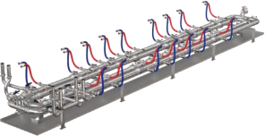
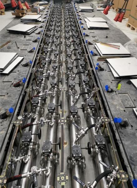
Factory prefabrication of secondary-side distribution pipework.
Factory preparation and cleanliness requirements
StageSource requirement
DesignStainless-steel pipes and valves with quick sanitary clamp connections; project-specific economical, low-resistance design
SimulationPressure-drop testing under business load and partial-fault conditions
PrefabricationFactory forming and prefabrication
InspectionFactory pressure-holding leak test and weld inspection
IdentificationDisassemble and number pipe spools after testing
Ultrasonic cleaningClean after disassembly; seal cleaned spools with cling film for transport
Pickling / passivationStrict removal of welding oxide scale
After pickling / passivation cleaningElectrical conductivity ≤10 μS/cm; dry afterward
Circulating flushPure water with electrical conductivity ≤10 μS/cm
Final inspectionInspect water quality after cleaning; dry pipework

Reference conditions & selection notes

  • Conductivity ≤10 μS/cm is the stated post-cleaning / flushing requirement. It is not declared as the universal operating-coolant conductivity limit.
  • Pipe sizing and pressure-drop validation depend on the project layout, server resistance, operating load and partial-fault cases.

Liquid Cooling Manual, pp. 31–32

Liquid Cooling Temperature Control System

System integration and controls

Liquid Cooling Temperature Control System

The temperature-control system connects the external cold source, primary-side pipework, CDU and controls, secondary-side pipework and server distribution. The distributed cold-plate arrangement includes a cold source, rack-mounted CDU, primary-side pipelines, cooling medium, liquid-cooled cabinet, liquid distributor, fluid connectors, cold plates, hydraulic hose assemblies and liquid-cooled backplanes. Immersion systems add a tank or cabinet, fluid replenishment and solution recovery. Selection starts with the server heat load, required inlet-fluid conditions and permitted pressure drop.

How it works

In a cold-plate circuit, the circulating pump supplies cooled secondary fluid to the server cold plates. The coolant absorbs component heat and returns through the distribution unit and secondary pipework to the CDU plate heat exchanger. The primary circuit transfers that heat to a cooling tower, dry cooler or chiller. The air-cooling channel removes remaining server heat through IDEC, DPC, a coil air wall, a liquid-cooled door or another suitable air system. In immersion cooling, the source distinguishes single-phase and phase-change server/tank arrangements.

Discuss this product
Features & technical specifications10 specification tables

Product features

  • Temperature-control functional tests include supply-liquid temperature, differential pressure and temperature regulation.
  • Dual-pump switching, make-up pump start/stop and circulation-pump operation control.
  • Automatic fluid make-up, liquid-leakage detection and anti-condensation control.
  • Manual control; automatic restart after power recovery; dual-power-supply switching.
  • Conductivity alarm setpoint configuration.
  • Main-loop supply / return differential-pressure control.
  • Main-loop supply-liquid temperature control.
  • Control based on the hydraulically most unfavorable loop.
Cold source and CDU heat-exchange circuit, with cold-plate and immersion heat-removal paths.
Liquid-cooling technology routes
Heat-transfer routeTechnologySource-described equipment arrangement
IndirectCold-plate liquid coolingRack-mounted, cabinet-mounted or large CDU; air/liquid or liquid/liquid heat exchange as illustrated
DirectSpray liquid coolingDirect liquid-cooling route in source roadmap
DirectSingle-phase immersion liquid coolingImmersion tank; liquid/liquid heat exchange
DirectPhase-change immersion liquid coolingPhase-change immersion tank; liquid/liquid heat exchange
Temperature-control product coverage
No.CategorySource-defined equipment
1Cold sourceAbundant water: cooling tower; scarce water: evaporative dry cooler; special scenarios: chiller
2Primary-side pipelinePrimary-side pipeline and construction
3CDUCDU and control system
4Secondary-side pipelineSecondary-side pipeline and construction
5DistributionManifold
6ImmersionImmersion tank
Server-side design information required
Design inputSource requirement
Heat loadServer power and proportion of heat removed by liquid cooling
Liquid temperatureRequired inlet temperature and permitted temperature range
Wetted connectionsMaterial requirements for inlet / outlet connections
HydraulicsInternal server pressure drop, pressure-bearing capacity and inlet flow
External connectionInterface specification and model
Air channelServer air inlet and outlet temperatures
Cold-plate and immersion system scope
ArchitectureSource equipment scope
Cold plateDry / evaporative full free-cooling cold source; centralized / distributed temperature-control unit; prefabricated clean network and distribution unit; standard liquid-cooled cabinet with intelligent control
ImmersionDry / evaporative full free-cooling cold source; centralized / distributed temperature-control unit; immersion tank / cabinet and prefabricated pipe network; fluid replenishment, solution recovery and intelligent control
Combined air and liquid heat-removal architecture
ChannelSource-described share of server heatCooling arrangement
Liquid50–90%Direct CPU liquid cooling; source describes liquid-cooled servers with built-in heat-pipe heat-exchange modules
Air10–50%IDEC, DPC, coil air wall, liquid-cooled door or other air-side technology; chilled-water or refrigerant-based cold source
Air-side integration options
Cold-plate combinationAir-side cold source / condition
Coil air wallChilled water or refrigerant-based system
IDECShown as a combined architecture; source slide supplies no individual performance rating
Liquid-cooled rear doorChilled water; high-temperature water possible if cabinet permits high-temperature inlet air
Terminator air wallChilled water or refrigerant-based system
All-liquid extensionSource states compressor mechanical refrigeration may be avoided; depends on permissible inlet conditions and cold source
Distributed cold-plate source performance statements
ItemSource statement (slide 1)
Single-point heat dissipationExceeds 700 W
Cabinet densityCan increase by 50%
PUE<1.1
Reliability designN+1; three-level anti-leakage design; liquid separated from electronic components
Chip temperature comparison20–30°C below the cited air-cooling comparison; source describes longer equipment life and support for overclocking
Noise comparisonMore than 30 dB reduction versus the cited air-cooled comparison
DeploymentFactory manufacturing, assembly and testing; on-site pipeline/cable connections; modular deployment
Technology overview reference statements
ItemSource reference statement (image-only slide 13)
Liquid volumetric heat capacity relative to air1000–3500 times
Thermal conductivity relative to air20–30 times
Precision coolingComponent-level cooling
PUE reference range1.05–1.2
Noise referenceAs low as 50 dB with no compressor and no or low-speed fans
Space reference50–80% space savings through increased cabinet density
Technology distinctionIndirect cold-plate cooling; direct single-phase or phase-change immersion cooling
Third-party cold-plate schematic reference
ParameterSugon reference illustration (image-only slide 14)
Server / internal-circuit supply water40–55°C
Server / internal-circuit return water50–65°C
Outer-circuit supply water35–50°C
Outer-circuit return water45–60°C
Liquid-section PUE reference<1.1
Air / liquid hybrid PUE reference<1.2
Reference flow pathCold plates → horizontal distribution manifold → vertical distribution manifold (VCDU) → CDU heat exchanger / pump → closed cooling tower (compressor-free in schematic)
Control functions and granularity
CategorySource function
Functional testsSupply-fluid temperature, differential pressure and temperature-regulation test
Pump functionsDual-pump changeover, make-up pump start / stop, circulation-pump operation
Fluid protectionAutomatic make-up, leakage detection, anti-condensation
Operating modesManual operation and auto-restart after power recovery
PowerDual-power-supply changeover
Water qualityConductivity alarm setpoint
Loop controlSupply / return differential pressure in main loop
Temperature controlMain-loop supply-fluid temperature
Hydraulic coverageMost unfavorable loop control

Applications

Cold-plate liquid-cooled data centers · Immersion liquid-cooled data centers · Retrofits requiring a combined air and liquid heat-removal architecture · Intelligent computing and AI clusters · Retrofitted data centers with increased capacity · Small-scale computing centers and small computer rooms · Small and micro AI training clusters · High-power-density equipment and research laboratories

Reference conditions & selection notes

  • Image-only slides 13 and 14 contain technical content. Slide 14 is explicitly a Sugon reference schematic; its temperatures and PUE values are not Cooltechx product ratings or promises.
  • The slide 1 distributed-system claims (>700 W per point, PUE <1.1, +50% cabinet density, 20–30°C chip-temperature reduction and >30 dB noise reduction) lack a defined test boundary in the source. They are reference statements requiring project confirmation; the source phrase near-zero leakage risk is a design claim rather than a quantified guarantee.
  • Slide 13 claims broad year-round natural cooling and cites PUE 1.05–1.2, 50 dB noise and 50–80% space savings without fluid, climate or load conditions. These are technology-overview examples, not universal outcomes.
  • PUE values have different source scopes: distributed cold plate <1.1 on slide 1; overview 1.05–1.2 on slide 13; Sugon liquid section <1.1 and hybrid <1.2 on slide 14; ACM system ≤1.13 on slide 25. They must not be combined into one guaranteed rating.
  • The liquid share of 50–90% and air share of 10–50% are architectural guidance; select the heat split from the actual server. The server inlet temperature, pressure and material requirements govern the final design.
  • The source uses the term heat-pipe heat-exchange modules on slide 18; it is retained as source wording and does not establish the construction of every compatible server.
  • The source overview names free-cooling cold sources for cold-plate and immersion systems. Annual availability and compressor-free operation require assessment of weather, water resources, server temperature limits and the remaining air-side cooling load.

Liquid Cooling Manual, pp. 1 and 12–20, 24, 28 and 33; pp. 13–14 include reference illustrations

Equipment selection starts with your site.

Let’s define your cooling system.

Talk to an engineer
Scroll to Top