
System integration and controls
Liquid Cooling Temperature Control System
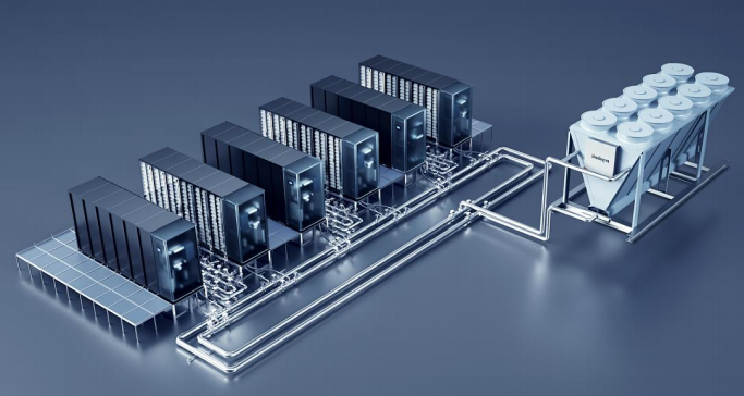
The temperature-control system connects the external cold source, primary-side pipework, CDU and controls, secondary-side pipework and server distribution. The distributed cold-plate arrangement includes a cold source, rack-mounted CDU, primary-side pipelines, cooling medium, liquid-cooled cabinet, liquid distributor, fluid connectors, cold plates, hydraulic hose assemblies and liquid-cooled backplanes. Immersion systems add a tank or cabinet, fluid replenishment and solution recovery. Selection starts with the server heat load, required inlet-fluid conditions and permitted pressure drop.
How it works
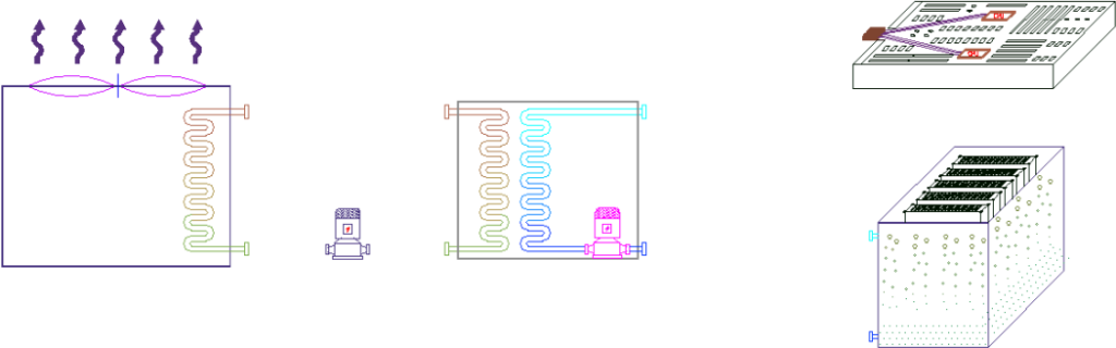
In a cold-plate circuit, the circulating pump supplies cooled secondary fluid to the server cold plates. The coolant absorbs component heat and returns through the distribution unit and secondary pipework to the CDU plate heat exchanger. The primary circuit transfers that heat to a cooling tower, dry cooler or chiller. The air-cooling channel removes remaining server heat through IDEC, DPC, a coil air wall, a liquid-cooled door or another suitable air system. In immersion cooling, the source distinguishes single-phase and phase-change server/tank arrangements.
Discuss this productFeatures & technical specifications10 specification tables
Product features
- Temperature-control functional tests include supply-liquid temperature, differential pressure and temperature regulation.
- Dual-pump switching, make-up pump start/stop and circulation-pump operation control.
- Automatic fluid make-up, liquid-leakage detection and anti-condensation control.
- Manual control; automatic restart after power recovery; dual-power-supply switching.
- Conductivity alarm setpoint configuration.
- Main-loop supply / return differential-pressure control.
- Main-loop supply-liquid temperature control.
- Control based on the hydraulically most unfavorable loop.
| Heat-transfer route | Technology | Source-described equipment arrangement |
|---|---|---|
| Indirect | Cold-plate liquid cooling | Rack-mounted, cabinet-mounted or large CDU; air/liquid or liquid/liquid heat exchange as illustrated |
| Direct | Spray liquid cooling | Direct liquid-cooling route in source roadmap |
| Direct | Single-phase immersion liquid cooling | Immersion tank; liquid/liquid heat exchange |
| Direct | Phase-change immersion liquid cooling | Phase-change immersion tank; liquid/liquid heat exchange |
| No. | Category | Source-defined equipment |
|---|---|---|
| 1 | Cold source | Abundant water: cooling tower; scarce water: evaporative dry cooler; special scenarios: chiller |
| 2 | Primary-side pipeline | Primary-side pipeline and construction |
| 3 | CDU | CDU and control system |
| 4 | Secondary-side pipeline | Secondary-side pipeline and construction |
| 5 | Distribution | Manifold |
| 6 | Immersion | Immersion tank |
| Design input | Source requirement |
|---|---|
| Heat load | Server power and proportion of heat removed by liquid cooling |
| Liquid temperature | Required inlet temperature and permitted temperature range |
| Wetted connections | Material requirements for inlet / outlet connections |
| Hydraulics | Internal server pressure drop, pressure-bearing capacity and inlet flow |
| External connection | Interface specification and model |
| Air channel | Server air inlet and outlet temperatures |
| Architecture | Source equipment scope |
|---|---|
| Cold plate | Dry / evaporative full free-cooling cold source; centralized / distributed temperature-control unit; prefabricated clean network and distribution unit; standard liquid-cooled cabinet with intelligent control |
| Immersion | Dry / evaporative full free-cooling cold source; centralized / distributed temperature-control unit; immersion tank / cabinet and prefabricated pipe network; fluid replenishment, solution recovery and intelligent control |
| Channel | Source-described share of server heat | Cooling arrangement |
|---|---|---|
| Liquid | 50–90% | Direct CPU liquid cooling; source describes liquid-cooled servers with built-in heat-pipe heat-exchange modules |
| Air | 10–50% | IDEC, DPC, coil air wall, liquid-cooled door or other air-side technology; chilled-water or refrigerant-based cold source |
| Cold-plate combination | Air-side cold source / condition |
|---|---|
| Coil air wall | Chilled water or refrigerant-based system |
| IDEC | Shown as a combined architecture; source slide supplies no individual performance rating |
| Liquid-cooled rear door | Chilled water; high-temperature water possible if cabinet permits high-temperature inlet air |
| Terminator air wall | Chilled water or refrigerant-based system |
| All-liquid extension | Source states compressor mechanical refrigeration may be avoided; depends on permissible inlet conditions and cold source |
| Item | Source statement (slide 1) |
|---|---|
| Single-point heat dissipation | Exceeds 700 W |
| Cabinet density | Can increase by 50% |
| PUE | <1.1 |
| Reliability design | N+1; three-level anti-leakage design; liquid separated from electronic components |
| Chip temperature comparison | 20–30°C below the cited air-cooling comparison; source describes longer equipment life and support for overclocking |
| Noise comparison | More than 30 dB reduction versus the cited air-cooled comparison |
| Deployment | Factory manufacturing, assembly and testing; on-site pipeline/cable connections; modular deployment |
| Item | Source reference statement (image-only slide 13) |
|---|---|
| Liquid volumetric heat capacity relative to air | 1000–3500 times |
| Thermal conductivity relative to air | 20–30 times |
| Precision cooling | Component-level cooling |
| PUE reference range | 1.05–1.2 |
| Noise reference | As low as 50 dB with no compressor and no or low-speed fans |
| Space reference | 50–80% space savings through increased cabinet density |
| Technology distinction | Indirect cold-plate cooling; direct single-phase or phase-change immersion cooling |
| Parameter | Sugon reference illustration (image-only slide 14) |
|---|---|
| Server / internal-circuit supply water | 40–55°C |
| Server / internal-circuit return water | 50–65°C |
| Outer-circuit supply water | 35–50°C |
| Outer-circuit return water | 45–60°C |
| Liquid-section PUE reference | <1.1 |
| Air / liquid hybrid PUE reference | <1.2 |
| Reference flow path | Cold plates → horizontal distribution manifold → vertical distribution manifold (VCDU) → CDU heat exchanger / pump → closed cooling tower (compressor-free in schematic) |
| Category | Source function |
|---|---|
| Functional tests | Supply-fluid temperature, differential pressure and temperature-regulation test |
| Pump functions | Dual-pump changeover, make-up pump start / stop, circulation-pump operation |
| Fluid protection | Automatic make-up, leakage detection, anti-condensation |
| Operating modes | Manual operation and auto-restart after power recovery |
| Power | Dual-power-supply changeover |
| Water quality | Conductivity alarm setpoint |
| Loop control | Supply / return differential pressure in main loop |
| 온도 제어 | Main-loop supply-fluid temperature |
| Hydraulic coverage | Most unfavorable loop control |
Applications
Cold-plate liquid-cooled data centers · Immersion liquid-cooled data centers · Retrofits requiring a combined air and liquid heat-removal architecture · Intelligent computing and AI clusters · Retrofitted data centers with increased capacity · Small-scale computing centers and small computer rooms · Small and micro AI training clusters · High-power-density equipment and research laboratories
Reference conditions & selection notes
- Image-only slides 13 and 14 contain technical content. Slide 14 is explicitly a Sugon reference schematic; its temperatures and PUE values are not Cooltechx product ratings or promises.
- The slide 1 distributed-system claims (>700 W per point, PUE <1.1, +50% cabinet density, 20–30°C chip-temperature reduction and >30 dB noise reduction) lack a defined test boundary in the source. They are reference statements requiring project confirmation; the source phrase near-zero leakage risk is a design claim rather than a quantified guarantee.
- Slide 13 claims broad year-round natural cooling and cites PUE 1.05–1.2, 50 dB noise and 50–80% space savings without fluid, climate or load conditions. These are technology-overview examples, not universal outcomes.
- PUE values have different source scopes: distributed cold plate <1.1 on slide 1; overview 1.05–1.2 on slide 13; Sugon liquid section <1.1 and hybrid <1.2 on slide 14; ACM system ≤1.13 on slide 25. They must not be combined into one guaranteed rating.
- The liquid share of 50–90% and air share of 10–50% are architectural guidance; select the heat split from the actual server. The server inlet temperature, pressure and material requirements govern the final design.
- The source uses the term heat-pipe heat-exchange modules on slide 18; it is retained as source wording and does not establish the construction of every compatible server.
- The source overview names free-cooling cold sources for cold-plate and immersion systems. Annual availability and compressor-free operation require assessment of weather, water resources, server temperature limits and the remaining air-side cooling load.
Liquid Cooling Manual, pp. 1 and 12–20, 24, 28 and 33; pp. 13–14 include reference illustrations